
Flexible shafts: Boosting machinery efficiency in 2026
20 April 2026
TL;DR:
- Flexible shafts operate at over 90% efficiency and excel in compact, misaligned, and vibration-sensitive applications.
- Advances include miniaturization, sensor integration, and predictive maintenance, supporting Industry 4.0 trends.
- Proper installation, alignment, and ongoing inspection are critical for maximizing flexible shaft performance and lifespan.
Flexible shafts carry a reputation for being a mature, even unremarkable component. That assumption is increasingly wrong. In 2026, flexible shaft technology is a precision engineering tool operating at over 90% efficiency in robotics, CNC machinery, aerospace assemblies, and advanced finishing systems. As machine envelopes shrink and performance requirements climb, design engineers and R&D teams are rediscovering flexible shafts not as a compromise, but as a deliberate, high-performance choice. This article covers the core principles, current technology trends, comparative performance data, and integration best practices every engineer needs to evaluate flexible shafts for 2026 machinery programs.
Table of Contents
- Understanding flexible shafts: Core principles and advantages
- Flexible shafts in 2026: Technology trends and innovation
- Flexible shafts versus rigid shafts and belts: Making the right choice
- Best practices for integrating flexible shafts in advanced machinery
- A new era for flexible shafts: What most engineers overlook
- Explore advanced flexible shaft solutions
- Frequently asked questions
Key Takeaways
| Point | Details |
|---|---|
| Exceeds 90% efficiency | Flexible shafts provide remarkable efficiency and less power loss for industrial machinery. |
| 2026 tech trends | Sensor-embedded smart shafts and miniaturized designs are driving new applications. |
| Critical comparison | Choosing between flexible, rigid, or belt drive systems depends on efficiency, alignment, and distance needs. |
| Implementation best practices | Apply precise alignment, predictive maintenance, and design frameworks for optimal performance. |
Understanding flexible shafts: Core principles and advantages
A flexible shaft is a mechanical drive element that transmits torque and rotational motion through a curved or angled path. Unlike rigid shafts, which require precise linear alignment between power source and tool, a flexible shaft routes power through bends, offsets, and tight geometries. The core consists of multiple layers of helically wound wire, which give the shaft its torsional stiffness while allowing lateral flexibility. A protective sheath surrounds the core, providing structural support and containment.
This design delivers several performance advantages that are directly relevant to machine design efficiency:
- High power transmission efficiency: Well-engineered flexible shafts exceed 90% efficiency, comparable to direct-drive rigid shafts in many applications.
- Bidirectional operation: Properly designed cores transmit torque in both rotational directions, a critical feature for reversible tools and multi-function assemblies.
- Power loss minimization: Bidirectional shaft designs minimize power loss, which can reach up to 30% in poorly matched or unidirectional configurations.
- Compact routing: Shafts navigate around obstructions, through curved conduits, and into confined spaces without additional gearboxes or universal joints.
- Vibration isolation: The flexible core naturally dampens torsional and radial vibration between the drive and the driven tool.
These properties make flexible shafts a logical choice for engineering compact drive solutions in robotics end-effectors, CNC spindle feeds, automotive assembly tooling, and aerospace actuators where rigid shaft geometry simply does not fit the design envelope.
“The shaft’s flexibility is a functional asset, not a mechanical limitation. Efficiency, compactness, and vibration control are built into the design from the ground up.”
Pro Tip: When specifying a flexible shaft, confirm the minimum bend radius for your routing path before finalizing the core diameter. Exceeding the rated bend radius degrades efficiency and accelerates wear on the outer sheath and inner wire layers.
The underlying mechanics are straightforward. Higher core density and tighter wire layering increase torsional rigidity and torque capacity. Larger core diameters handle higher loads but require greater bend radii. Matching core construction to the actual torque, RPM, and bend radius requirements of the application is the single most impactful decision in the specification process.
Flexible shafts in 2026: Technology trends and innovation
Flexible shaft technology is not static. Current development priorities are pushing three specific directions: miniaturization, sensor integration, and smart predictive maintenance capability. Each of these aligns directly with where advanced industrial manufacturing is heading in 2026.
Miniaturization is driven by demand for smaller, lighter machine assemblies without sacrificing power density. Manufacturers are producing customized cores with tighter wire tolerances and higher-grade alloys, achieving greater torque-per-diameter ratios than previous generations. This makes flexible shafts viable in micro-machining and surgical device applications where space constraints are extreme.

Sensor integration is the more transformative development. Embedded sensors in the shaft assembly or sheath interface now allow real-time monitoring of torque load, temperature, and rotational speed. This data feeds directly into predictive maintenance systems, enabling condition-based service intervals rather than fixed schedules. The result is reduced unplanned downtime and longer component service life.
Market context: Flexible manufacturing systems are projected to reach $22.2 billion by 2030, with precision and miniaturization demand rising sharply. Smart shafts with integrated sensors for predictive maintenance represent one of the fastest-growing segments within this market.
The table below summarizes the functional differences between traditional and next-generation flexible shaft designs:
| Feature | Traditional flexible shaft | 2026-generation flexible shaft |
|---|---|---|
| Core material | Standard carbon steel wire | High-grade alloy wire, precision tolerances |
| Sensor integration | None | Embedded torque, temp, RPM sensors |
| Maintenance model | Fixed schedule | Condition-based, predictive |
| Torque-per-diameter | Standard ratio | Improved, higher power density |
| Application range | General industrial | Micro-machining, robotics, medical devices |
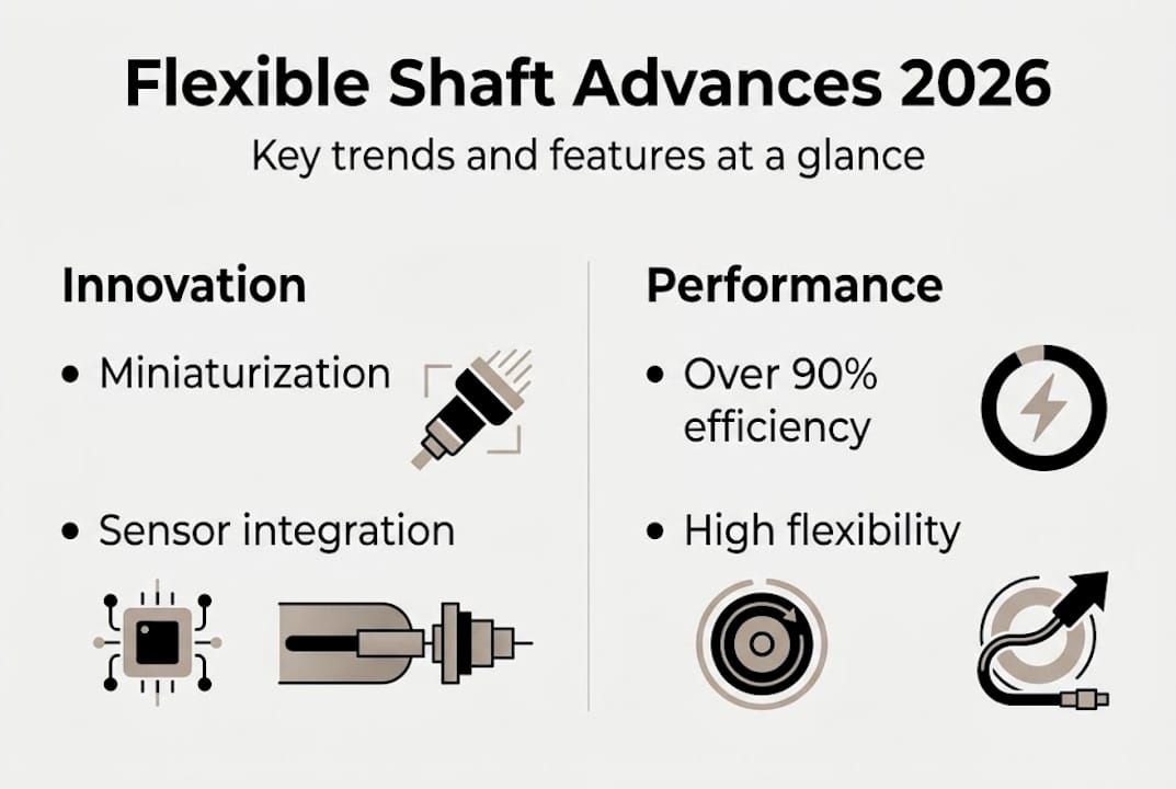
For design engineers reviewing 2026 flexible shaft trends, the practical implication is clear: specifications written for 2020 programs may underestimate what current flexible shaft technology can do. Reviewing torque, RPM, and integration requirements against updated product capabilities is worth the engineering time.
Key application sectors seeing the strongest adoption include:
- Collaborative robotics: Lightweight flexible shafts enable compact wrist and elbow joint drives.
- CNC finishing: Flexible shafts power deburring, grinding, and polishing heads with consistent torque delivery.
- Automotive assembly: High-cycle flexible shaft applications in torque tool drive lines are replacing multi-component rigid linkages.
Flexible shafts versus rigid shafts and belts: Making the right choice
Each drive system has a performance envelope. Selecting the wrong one for a given application costs efficiency, service life, and machine uptime. Here is a direct comparison of the three primary options for design engineers evaluating 2026 machinery configurations.
| Criterion | Flexible shaft | Rigid shaft | Belt drive |
|---|---|---|---|
| Misalignment tolerance | High | Very low | Moderate |
| Vibration dampening | Good | Poor | Moderate |
| Power transmission efficiency | Over 90% | Up to 99% | 85-95% |
| Long-distance transmission | Limited | Good | Excellent |
| Compact routing capability | Excellent | None | Moderate |
| Maintenance complexity | Low to moderate | Low | Moderate |
| Bidirectional capability | Yes (design dependent) | Yes | Limited |
Flexible shafts outperform rigid shafts where misalignment or geometric constraints exist. However, precise initial alignment at the coupling interfaces remains critical even for flexible systems. Allowing excessive angular or axial offset at the connection points introduces cyclic stress and reduces service life, regardless of how well the shaft itself handles mid-path curvature.
Belt drives remain the preferred choice when power must be transmitted over distances greater than roughly 1 to 2 meters, or when speed ratios between source and load must be easily changed. Flexible shafts are not competitive in these scenarios.
For practical decision-making, consider the following criteria in order:
- Routing geometry: If the power path cannot be made straight, a flexible shaft is the primary candidate.
- Vibration sensitivity: If the driven tool or process is sensitive to transmitted vibration, flexible shafts provide inherent isolation.
- Distance requirements: If transmission distance exceeds the practical shaft length for the application, evaluate belt or chain drives.
- Efficiency priority: If efficiency above 95% is mandatory and straight-line routing is possible, a rigid shaft or precision coupling may be more appropriate.
- Maintenance access: If the drive is located in a confined space with limited service access, flexible shafts with low-maintenance sheaths reduce lifecycle costs.
For a detailed review of benefits of flexible shafts versus competing solutions, the selection criteria above provide a reliable starting point.
Pro Tip: Avoid flexible shafts in applications with continuous full-load operation at maximum rated torque for extended periods without rest cycles. Continuous high-torque use without cooling intervals can degrade the inner wire layers and sheath prematurely.
Best practices for integrating flexible shafts in advanced machinery
Selecting the right flexible shaft is necessary but not sufficient. Integration quality determines real-world performance. The following framework addresses the full process from specification through ongoing maintenance.
- Define torque and RPM requirements precisely. Work from measured load data, not estimates. Over-specifying adds cost and weight; under-specifying leads to premature failure.
- Confirm minimum bend radius for the routing path. Map the full shaft path in the assembly model before finalizing shaft selection. Account for all bends, offsets, and dynamic movement during operation.
- Select appropriate coupling interfaces. Coupling type and fit quality at both ends directly affect transmitted efficiency and wear rate. Standard square drives, hex fittings, or custom coupling interfaces should be matched to the shaft specification.
- Perform precise alignment at coupling points. Flexible couplings require accurate angular and axial positioning at the connection interfaces. Misalignment at the coupling introduces bending loads the shaft core was not designed to handle.
- Secure the sheath correctly. Sheath end fittings must be anchored to prevent rotation and axial movement. Unsecured sheaths transmit torque reaction forces to the machine frame, causing noise and wear.
- Establish a maintenance inspection schedule. Even low-maintenance flexible shafts benefit from periodic inspection of sheath condition, coupling wear, and lubrication status.
“Proper sheath mounting and coupling alignment at installation are the two factors that most frequently determine whether a flexible shaft reaches or falls short of its rated service life.”
Pro Tip: For applications involving sensor-integrated shafts, establish baseline torque and temperature data during commissioning. Deviations from this baseline during service are the earliest indicator of developing faults, allowing intervention before failure.
For engineers working through the detailed shaft design steps for a specific program, structured design review at the specification, installation, and commissioning stages significantly reduces field problems. BIAX Flexwellen supports machine builders through this process, from custom flexible shaft design to standard component selection.
A new era for flexible shafts: What most engineers overlook
Conventional design thinking focuses on what is visible: motors, gearboxes, couplings, and the driven tool. Flexible shafts occupy the space between these elements and are often treated as a routing convenience rather than a performance variable. That is a costly oversight.
The real opportunity in 2026 lies in treating the flexible shaft as an active design parameter, not a passive connector. Sensor-enabled shafts now generate data that can feed back into design optimization, revealing actual load profiles, duty cycles, and thermal conditions that static analysis cannot predict. Engineers who use this data improve not just the shaft but the entire machine’s reliability model.
There is also a timing argument. The adoption curve for sensor-integrated flexible shafts in robotics and precision manufacturing is still in its early phase. Teams that build competency in specifying and integrating these systems now will carry a real design advantage into the next generation of machinery programs. Waiting for the technology to mature further means ceding that advantage to competitors who are already building experience.
The component is no longer just flexible. It is increasingly intelligent.
Explore advanced flexible shaft solutions
BIAX Flexwellen offers a full range of standard and custom flexible shaft solutions engineered for demanding industrial applications. Whether the requirement is deburring in a confined robotic cell, high-cycle grinding in an automated line, or a custom torque and RPM configuration for a specialized machine, the product portfolio and engineering support are structured to address it. Review the full scope of industrial flexible shaft applications for application-specific guidance, or explore custom shaft design solutions to discuss specific coupling interfaces, shaft geometry, and load requirements. For direct technical support, speak with our shaft experts to align the right solution with your 2026 machinery program.
Frequently asked questions
What makes flexible shafts more efficient than belt drives in manufacturing?
Flexible shafts deliver over 90% efficiency while reducing power loss, particularly in compact and bidirectional setups where belt drives introduce slip and alignment losses.
How are flexible shafts supporting Industry 4.0 trends in 2026?
Smart flexible shafts with integrated sensors enable predictive maintenance and real-time load monitoring, with the broader flexible manufacturing market projected to reach $22.2 billion by 2030.
What are the biggest limitations of flexible shafts compared to rigid shafts or belts?
Flexible shafts handle misalignment and vibration well but are less suited for long-distance transmission, and precise coupling alignment remains necessary even in flexible configurations.
What maintenance considerations are unique to flexible shafts in advanced machinery?
Proper initial alignment at the coupling interfaces and routine condition monitoring are the primary factors that determine service life, especially in sensor-equipped shafts where baseline torque data established at commissioning serves as the reference for fault detection.
Recommended
- Flexible Shafts in Manufacturing: Precision & 2026 Insights – BIAX Flexwellen
- How flexible shafts improve machine design efficiency
- Flexible Shafts for Tight Spaces: Boosting Precision
- Flexible Shaft Drive Solutions: Unlocking Compact Efficiency
- Global Industrie Lyon 2026 : L’industrie de demain au BTP
Related Topics
Send your spec inquiry
Custom flexible shafts for your application — we quote within 1 working day.


