Why flexible drives deliver reliable performance for engineers
21 April 2026TL;DR:
- Flexible drive components enhance system reliability by absorbing misalignment and damping vibrations.
- They extend bearing life, reduce maintenance, and improve machine uptime compared to rigid drives.
- Appropriate application of flexible drives supports predictive maintenance and adapts to changing manufacturing conditions.
Equipment misalignment and vibration are responsible for up to 50% of rotating machinery failures in industrial plants. Yet many design and production engineers continue to specify rigid drive systems as the default, assuming they offer superior precision and longevity. That assumption is worth questioning. Flexible drive components have matured significantly as an engineering discipline, and the performance data now supports a clear case for their adoption in a wide range of manufacturing environments. This guide covers what flexible drive components are, how they compare to rigid alternatives, and where they deliver the most measurable value for system reliability and uptime.
Table of Contents
- What are flexible drive components?
- Performance benefits of flexible drive components in manufacturing
- Comparing flexible vs. rigid drive options: What engineers need to know
- Application highlights: Where flexible drive components excel
- Our experience: What most guides miss about flexible drive decisions
- Get engineering support for your flexible drive projects
- Frequently asked questions
Key Takeaways
| Point | Details |
|---|---|
| Adaptability to misalignment | Flexible drive components can handle shaft misalignment, reducing failure risk in complex assemblies. |
| Maintenance and longevity | They extend equipment life and ease maintenance by limiting vibration-induced wear and enabling predictive care. |
| Performance in challenging applications | Flexible drives excel in robotics, compact machinery, and high-vibration environments where rigid shafts struggle. |
| Evidence-backed decision making | Recent research proves flexible couplings help detect faults early and prevent major downtime. |
What are flexible drive components?
Flexible drive components are mechanical transmission elements designed to transfer torque and rotational motion between a drive source and an output device while accommodating positional offsets, angular deviations, and vibration loads. Unlike rigid shafts or couplings that require near-perfect alignment, flexible components tolerate a defined range of misalignment without transmitting damaging loads to connected bearings or housings.
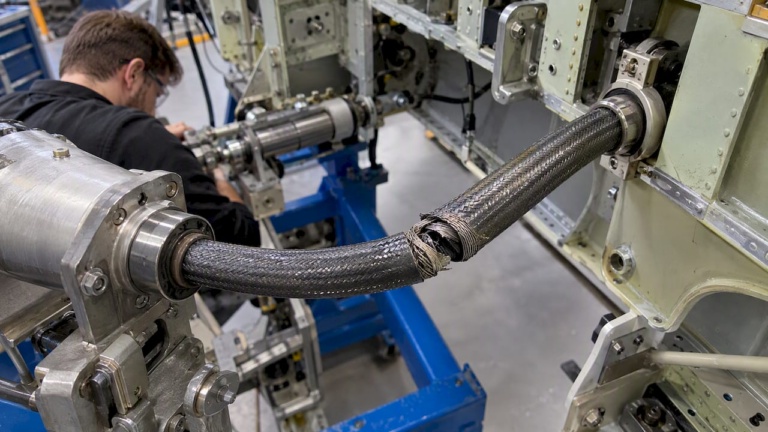
The most common formats include flexible shafts, flexible couplings, and articulated drive assemblies. Flexible shafts consist of a helically wound core, typically made from high-tensile steel wire, enclosed within a protective sheath. The sheath guides the shaft and contains lubrication to reduce friction during operation. Couplings, by contrast, connect two shaft ends and rely on elastomeric inserts or mechanical articulation to absorb angular and parallel misalignment.
Compared to rigid drives, flexible components offer key structural differences:
- Tolerance to angular misalignment: Flexible shafts and couplings absorb angular offsets without generating reactive forces on bearings.
- Vibration damping: Elastomeric and wound-core designs attenuate vibration transmitted along the drive train.
- Spatial adaptability: Flexible shafts can route torque around obstacles or through confined spaces where rigid shafts cannot be installed.
- Reduced installation sensitivity: Flexible components do not require precision alignment fixtures during assembly, which cuts installation time.
Common failure scenarios where rigid drives underperform include thermal expansion in heated production lines, frame deflection in mobile or lightly constructed machinery, and positional drift in multi-axis automation equipment. In each case, a rigid connection converts misalignment directly into bearing load, accelerating wear.
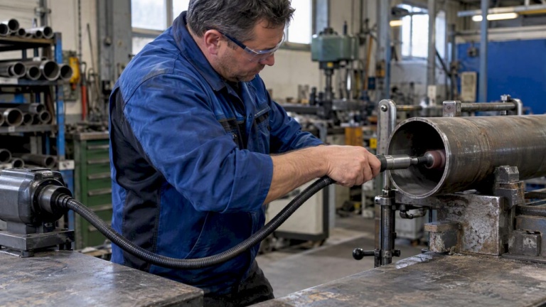
For engineers working on engineering compact drive solutions, flexible shafts are particularly effective where the drive source and tool head cannot share a common axis, such as in deburring tools, remote actuation systems, and instrumentation.
Pro Tip: One of the most overlooked application scenarios is static misalignment caused by manufacturing tolerances stacking up across an assembly. Engineers often account for dynamic misalignment from vibration but neglect the cumulative positional offset from part-to-part variation. Flexible components handle both simultaneously.
Performance benefits of flexible drive components in manufacturing
With a clear understanding of what flexible drive components are, let’s examine how they actually perform in manufacturing environments.
The primary operational advantage of flexible drives is their effect on drivetrain longevity. Rigid connections transmit misalignment loads directly into bearing races, increasing contact stress and accelerating fatigue. Flexible components interrupt this load path. Research confirms that flexible couplings prevent bearing failures and support early fault detection through vibration analysis, allowing maintenance teams to identify developing issues before they cause unplanned downtime.
“Vibration analysis of systems equipped with flexible couplings enables detection of fault signatures that would otherwise be masked in rigidly coupled machines, enabling proactive maintenance scheduling.” — Based on findings from the Study on the Influence of Flexible Couplings in Rotor-Bearing Systems
For production engineers focused on machine design efficiency, the measurable cost benefits are equally significant:
- Lower bearing replacement frequency: Reduced misalignment loads extend mean time between failures (MTBF) for bearings by a measurable margin in high-cycle applications.
- Shorter maintenance windows: Flexible shaft assemblies are typically faster to replace than rigid shaft assemblies due to simpler disassembly.
- Reduced alignment labor at installation: No precision laser alignment is required, cutting commissioning time per machine.
- Improved uptime KPIs: Fewer unplanned stoppages translate directly into higher overall equipment effectiveness (OEE).
The table below compares key performance metrics between flexible and rigid drive systems in a representative manufacturing environment:
| Metric | Flexible drive | Rigid drive |
|---|---|---|
| Misalignment tolerance | High (angular and parallel) | Low (near-zero tolerance) |
| Vibration attenuation | Effective | Minimal |
| Bearing service life | Extended | Standard to reduced |
| Installation complexity | Low to moderate | Moderate to high |
| Maintenance frequency | Reduced | Standard to increased |
| Spatial routing flexibility | High | None |
For teams evaluating drive systems for manufacturing efficiency, these figures translate into lower total cost of ownership over the machine lifecycle. Engineers who have moved to implement flexible shaft drive solutions in high-vibration or thermally variable environments consistently report reductions in bearing-related downtime.

Comparing flexible vs. rigid drive options: What engineers need to know
Now that we grasp the performance benefits, it’s essential to compare flexible and rigid drives so you can confidently make the right choice for your system.
Misalignment is the central differentiator. Misalignment causes elevated 1x and 2x rotor speed vibration harmonics in rigid systems, which flexible couplings are specifically designed to suppress. This is not just a maintenance issue. Elevated vibration harmonics contribute to fatigue in fasteners, housings, and adjacent components, compounding the cost of a single misaligned shaft.

| Attribute | Flexible drive | Rigid drive |
|---|---|---|
| Misalignment handling | Angular and parallel | None practical |
| Durability in harsh environments | High (with correct spec) | Dependent on alignment quality |
| Precision at high RPM | Good with correct design | Excellent when aligned |
| Environmental tolerance | Higher | Lower |
| Lifecycle cost | Lower in most applications | Can be lower in ideal conditions |
| Maintenance demand | Periodic lubrication only | Alignment checks required |
Flexible drives are clearly superior in environments with: changing loads, thermal cycling, vibration from adjacent machinery, limited installation space, or remote actuation requirements. Rigid drives retain an advantage in very high precision positioning or where maximum torsional stiffness is essential, such as in servo-controlled CNC interpolation.
For engineers assessing boosting machinery efficiency through drivetrain choices, here is a structured evaluation process:
- Quantify misalignment range: Measure angular and parallel offset between drive and output shaft under operating conditions, including thermal expansion.
- Assess vibration environment: Identify vibration sources near the drive. High ambient vibration strongly favors flexible components.
- Map spatial constraints: Determine if the drive path requires routing around structures or through limited cross-sections.
- Define torque and RPM requirements: Ensure the flexible component’s rated torque exceeds peak load with a defined safety factor.
- Calculate lifecycle cost: Compare initial cost, alignment labor, bearing replacement frequency, and downtime costs between both options.
Pro Tip: The most common specification error is selecting a flexible coupling sized for average torque rather than peak torque. Peak loads during startup or load reversals can exceed steady-state torque by 2x to 3x, and undersized flexible components fail prematurely in exactly these transient events.
Application highlights: Where flexible drive components excel
To anchor the comparison in real practice, let’s review concrete applications where the advantages of flexible drive components become most apparent.
Flexible drives address specific failure modes that rigid systems cannot resolve without costly precision machining or redesign. The following application areas represent where shaft applications for manufacturing reliably outperform alternatives:
- Deburring and finishing tools: Hand-held or machine-mounted finishing tools require torque delivery to a head that must reach recessed or angled surfaces. Flexible shafts route torque to the point of use without requiring a rigid mechanical path.
- Conveyor drive systems: Frame deflection under load causes ongoing misalignment in long conveyor drives. Flexible couplings absorb positional drift without transferring stress to drive motors or gearboxes.
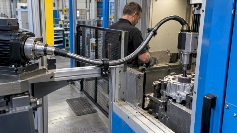
- Robotics end-effectors: In robotics applications, flexible shafts transmit actuation force to joints or grippers without requiring motors to be mounted at the point of action, reducing arm inertia and improving dynamic response.
- Remote actuation in compact machinery: Where a motor cannot be co-located with the driven component, flexible shafts bridge the spatial gap reliably.
- Agricultural and process equipment: Seasonal load variations and outdoor thermal cycling create conditions that rigid drives handle poorly.
From a predictive maintenance perspective, flexible couplings add direct diagnostic value. Research shows that flexible couplings detect faults early via vibration signature analysis, meaning sensors mounted on flexibly coupled shafts can identify imbalance, looseness, or developing bearing defects earlier than on rigidly coupled systems.
For production engineers tracking uptime KPIs, this early detection window directly supports scheduled maintenance intervals. Faults caught at the vibration anomaly stage allow repair during planned shutdowns rather than forcing emergency line stops.
Our experience: What most guides miss about flexible drive decisions
Most technical comparisons between flexible and rigid drives stop at the component level. They address torque ratings, misalignment angles, and material properties. What they rarely address is the lifecycle context in which these components operate.
In practice, the most costly drive failures we observe are not the result of selecting the wrong component category. They result from under-specifying flexible drives because the machine performed acceptably at commissioning. As machines accumulate hours, frame rigidity decreases, bearing clearances widen, and thermal cycling compounds positional drift. A flexible component specified to the original alignment condition may be operating near its limit within two to three years.
The second overlooked factor is load change. Production line reconfigurations, higher throughput targets, and new tooling frequently change the torque demand on existing drives without triggering a formal design review. A drive specified for one application profile quietly operates outside its original design envelope.
For engineers who want to protect their investment, the right time to evaluate flexible shaft technology benefits is not only at initial system design. It should also occur when throughput requirements change, when bearing replacement frequency increases, or when a machine enters a new operating environment.
Get engineering support for your flexible drive projects
Having explored both technical and practical perspectives, the next step is to access the resources and expertise needed for specific application challenges. BIAX Flexwellen supports design and production engineers with direct technical guidance on torque requirements, RPM specifications, coupling interfaces, and shaft routing for demanding industrial environments. Whether you are evaluating industrial flexible shaft applications for a new machine build or optimizing an existing drivetrain, our engineering team provides application-specific recommendations. For teams assessing manufacturing drive system benefits at a system level, our website offers detailed technical guides and direct inquiry support. Contact us to discuss your requirements.
Frequently asked questions
How do flexible drive components help prevent machine failure?
Flexible drive components absorb misalignment and dampen vibrations, reducing bearing load and enabling early fault detection. Research confirms that flexible couplings prevent bearing failures and support proactive maintenance through vibration analysis.
What types of applications benefit most from flexible drives?
Applications with changing loads, frequent misalignments, or space constraints benefit most. Systems using flexible couplings can also detect faults early via vibration analysis, making them well suited to predictive maintenance programs.
Can flexible drive components improve predictive maintenance?
Yes. Their design allows for continuous vibration monitoring and earlier anomaly detection. This capability, supported by research on flexible coupling fault detection, enables maintenance teams to schedule repairs during planned windows rather than reacting to failures.
Is there a trade-off in precision or durability when using flexible drives?
Modern flexible drives, when correctly specified for torque and RPM requirements, deliver excellent durability and precision. The trade-off only appears when flexible components are under-specified or misapplied to applications requiring maximum torsional stiffness.
Recommended
- Flexible shaft guide: Engineering compact drive solutions
- Flexible Shaft Drive Solutions: Unlocking Compact Efficiency
- Flexible Shafts Maintain 85-95% Efficiency in Tight Spaces
- 7 key advantages of flexible shaft machining for engineers
Related Topics
Send your spec inquiry
Custom flexible shafts for your application — we quote within 1 working day.