
Torsion and Torque Explained for Design Engineers
29 July 2026Torque is the external moment applied to a shaft; torsion is the internal twist) and shear state the shaft develops in response. That distinction drives every flexible-shaft specification: torque is the input you define, and torsional stiffness, shear stress, and angle of twist are the design responses you constrain. The primary torque equation is τ = r × F, where r is the moment arm (m) and F is the perpendicular force (N), giving torque in N·m.
Pro Tip: Treat torque as the input specification and torsional stiffness (k = G·J/L) as the design response. Locking down both prevents over-twist and phase error before a prototype is ever built. For custom flexible-shaft sizing, the Biax-flexwellen team can assist with initial specification — contact the engineering team directly.
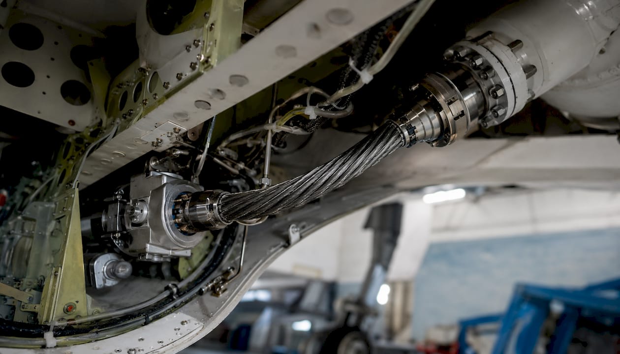
Table of Contents
- What are the core torsion and torque formulas engineers use?
- How does torsion govern shaft performance and failure?
- Worked example: shear stress and angle of twist for a hollow shaft
- Flexible shaft specification checklist
- Aerospace application notes: synchronization and phase error
- How to measure torque, twist, and torsional stress in prototypes
- Key Takeaways
- Why coupling geometry deserves more attention than shaft diameter
- Biax-flexwellen engineering support for flexible-shaft specifications
- Useful sources
What are the core torsion and torque formulas engineers use?
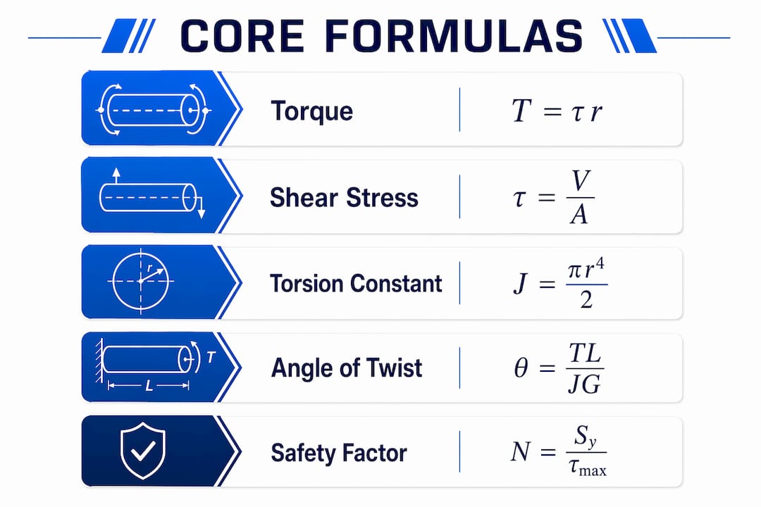
Four equations cover the majority of shaft design calculations. Each is listed below with its variables and SI units.
| Quantity | Formula | Units |
|---|---|---|
| Torque (moment of force) | τ = r × F | N·m |
| Shear stress under torsion | τ_shear = T·r / J | Pa (N/m²) |
| Angle of twist | φ = T·L / (G·J) | radians |
| Torsional stiffness | k = G·J / L | N·m/rad |
Variable definitions: T = applied torque (N·m); r = outer radius to point of interest (m); J = torsion constant (m⁴); G = shear modulus (Pa); L = shaft length (m); φ = angle of twist (rad).
Torsion constant J for circular sections
For circular shafts, J equals the polar moment of inertia:
| Cross-section | J formula |
|---|---|
| Solid circular (diameter d) | J = π·d⁴ / 32 |
| Hollow circular (outer d_o, inner d_i) | J = π·(d_o⁴ − d_i⁴) / 32 |
For non-circular cross-sections — splined profiles, rectangular cores, or multi-strand flexible assemblies — closed-form J values are not available. Handbook constants (Roark’s Formulas for Stress and Strain is the standard US reference) cover common shapes. For complex or integrated coupling geometries, finite element analysis) is the reliable path; standard formulas can underestimate local shear stress by a significant margin at stress concentrations.
How does torsion govern shaft performance and failure?
Torsional stiffness (k = G·J/L) and torque capacity are separate design constraints, and conflating them is a common specification error. Stiffness controls angular wind-up and phase error under load. Capacity, governed by the material’s shear yield strength and fatigue limit, controls whether the shaft survives the applied load cycle.
Torsional shear stress) is not uniform across a cross-section. For a solid circular shaft, stress is zero at the neutral axis and peaks at the outer surface. Hollow shafts exploit this distribution: removing material near the center reduces mass with minimal stiffness penalty. Non-circular sections develop warping in addition to shear, which complicates both the stress state and the J calculation.
Stress concentrations at keyways, coupling bores, and press-fit interfaces amplify local shear stress well above the nominal value. Common failure modes include torsional overload at the highest-stress cross-section, fatigue crack initiation at surface discontinuities under cyclic loading, and torsional resonance when the operating speed approaches a torsional natural frequency. Mitigations include generous fillet radii at shoulders and coupling interfaces, controlled surface finish (Ra ≤ 0.8 µm at critical zones is a common aerospace requirement), and coupling geometry selected to distribute load rather than concentrate it.
Pro Tip: In flexible shaft assemblies, the coupling or interface geometry frequently sets the allowable torque limit, not the shaft core itself. Specify fillet radii, bore tolerances, and stress-relief features at every interface before finalizing the shaft material or diameter.
Worked example: shear stress and angle of twist for a hollow shaft
The following example uses a hollow steel shaft under a steady torque. Values are chosen to be representative of a light industrial drive application.
1. State inputs
- Applied torque: T = 50 N·m
- Shaft length: L = 0.8 m
- Outer diameter: d_o = 20 mm = 0.020 m → outer radius r = 0.010 m
- Inner diameter: d_i = 14 mm = 0.014 m
- Shear modulus (steel): G = 80 GPa = 80 × 10⁹ Pa
- Allowable shear stress: τ_allow = 120 MPa
2. Compute J
J = π·(d_o⁴ − d_i⁴) / 32
J = π·((0.020)⁴ − (0.014)⁴) / 32
J = π·(1.600 × 10⁻⁷ − 3.842 × 10⁻⁸) / 32
J = π·(1.216 × 10⁻⁷) / 32
J ≈ 1.194 × 10⁻⁸ m⁴
3. Compute shear stress
τ_shear = T·r / J = 50 × 0.010 / 1.194 × 10⁻⁸
τ_shear ≈ 41.9 MPa
4. Compute angle of twist
φ = T·L / (G·J) = 50 × 0.8 / (80 × 10⁹ × 1.194 × 10⁻⁸)
φ = 40 / 955.2
φ ≈ 0.0419 rad ≈ 2.40°
5. Safety factor check
SF = τ_allow / τ_shear = 120 / 41.9 ≈ 2.86 — acceptable for continuous duty.
| Parameter | Value | Unit |
|---|---|---|
| Applied torque T | 50 | N·m |
| Outer radius r | 0.010 | m |
| Torsion constant J | 1.194 × 10⁻⁸ | m⁴ |
| Shear stress τ | 41.9 | MPa |
| Angle of twist φ | 0.0419 / 2.40° | rad / deg |
| Safety factor | 2.86 | — |
Unit consistency note: carry all dimensions in meters and pascals through the calculation, then convert to mm or MPa only in the final result row. Mixing mm and m mid-calculation is the most common source of order-of-magnitude errors on specification sheets.
Flexible shaft specification checklist
A complete specification covers both the shaft and its interfaces. Use the items below as a minimum set when submitting a shaft design request to a supplier.
- Required torque: continuous rating and peak (N·m); include duty cycle and shock factor
- Allowable angular error / phase shift: maximum acceptable twist between input and output ends (degrees or radians at operating torque)
- Torsional stiffness k: derived from allowable phase error and torque profile; state in N·m/rad
- Shaft length and routing: total length, minimum bend radius, and any routing constraints
- Maximum RPM: operating speed and any transient overspeed conditions
- Service factor: continuous (SF ≥ 1.5 typical), shock/impact duty (SF ≥ 2.5 or per applicable standard)
- Material and environment: operating temperature range, corrosion exposure, fluid compatibility
- Coupling interfaces: bore diameter, keyway or spline geometry, tolerance class, and fillet requirements
- Fatigue life target: number of load cycles or service hours; specify load spectrum if variable-amplitude
Pro Tip: For phase-critical systems, derive k directly from the allowable angular error: k = T / φ_max. In multi-actuator drive trains, account for cumulative wind-up across each shaft segment — the total phase error is additive.
For non-circular cross-sections or assemblies with welded or fitted couplings, request FEA-validated test data) from the supplier rather than relying on nominal material ratings alone.
Aerospace application notes: synchronization and phase error
In aerospace synchronization systems, flap and slat actuation shafts, thrust reverser sequencing drives, and valve override mechanisms all share one constraint: torsional wind-up must remain within a defined phase error budget throughout the load cycle. A shaft that meets its torque capacity requirement but exceeds its allowable twist can cause control surface asymmetry or sequencing faults.
Procurement and qualification checks for aerospace flexible shafts should include:
- Traceable material certifications (AMS or equivalent)
- Fatigue life test data at the specified load spectrum and temperature range
- Non-destructive inspection records (ultrasonic or dye-penetrant per applicable standard)
- Torque-vs.-angle curves measured at operating temperature extremes
- Interface design review confirming fillet geometry and tolerance stack-up
Confined installations add a further constraint. When envelope diameter is fixed, torsional stiffness becomes the primary design variable rather than capacity. Stepped shaft profiles, composite-reinforced cores, or specialized coupling geometries can recover stiffness within a tight envelope. For compact drive solutions in confined aerospace installations, verify k at the assembly level, not just at the shaft core.
Pro Tip: Request angular wind-up vs. torque curves measured at representative RPM and temperature from the supplier. Curves measured at room temperature and zero speed can understate wind-up by a meaningful margin under operating conditions.
How to measure torque, twist, and torsional stress in prototypes
Measurement methods should match the quantity being validated:
- Inline torque: rotary torque transducers (reaction or rotating) mounted between driver and load; rotary torque transducers give continuous torque data at operating speed
- Local shear stress: shear rosette strain gauges bonded at 45° to the shaft axis; circumferential gauges confirm surface shear at critical cross-sections
- Angle of twist / phase error: dual angle encoders at each shaft end; optical encoders with sub-arcminute resolution are standard for aerospace validation
- Torsional natural frequencies: modal testing with an impulse hammer or swept-sine excitation; compare measured resonant frequencies against operating speed range to confirm adequate separation margin
Suggested verification sequence: static torque-vs.-angle baseline, cyclic fatigue test at the specified duty cycle, thermal-environment test across the full temperature range, and modal survey. For long-run torque-transmission applications, periodic re-inspection intervals should be defined based on the fatigue life estimate.
Common pitfalls: torque sensor mounting compliance adding apparent twist to the shaft measurement; encoder misalignment introducing angular error that is attributed to the shaft; and strain gauge lead wires picking up electrical noise at high RPM. Always measure twist under the same boundary conditions — couplings, preload, and bearing arrangement — expected in the installed system.
Pro Tip: Lab fixtures that differ from field mounts give misleading twist measurements. Replicate the installed boundary conditions, including coupling compliance and bearing preload, before recording validation data.
Key Takeaways
Torque is the external input; torsion is the internal shear response — specifying both stiffness (k = G·J/L) and capacity (τ_shear = T·r/J) is required for a complete flexible-shaft design.
| Point | Details |
|---|---|
| Torque vs. torsion | Torque (τ = r × F) is the applied moment; torsion is the resulting internal shear and angular deformation. |
| Three core equations | τ = r × F; τ_shear = T·r/J; φ = T·L/(G·J) — carry all units in meters and pascals. |
| Stiffness and capacity | Specify torsional stiffness k and torque capacity separately; phase-critical systems require k derived from allowable angular error. |
| Coupling interfaces | Interface geometry often sets the allowable torque limit; specify fillet radii and tolerance class at every coupling. |
| Biax-flexwellen support | Biax-flexwellen provides engineering support, custom shaft configurations, and FEA-validated test data for torque-transmission specifications. |
Why coupling geometry deserves more attention than shaft diameter
Most engineers reach for shaft diameter as the primary design variable. In practice, the coupling interface controls allowable torque in the majority of OEM flexible-shaft failures. A shaft core sized to SF = 3.0 can fail at SF = 1.2 if the coupling bore has a sharp corner and an undersized fillet. The formulas in this article give correct nominal stress values, but nominal stress is not the stress that initiates fatigue cracks. Stress concentration factors at keyways, splines, and press-fit shoulders routinely multiply local shear stress by factors of 1.5–3.0 above the calculated value. Biax-flexwellen treats coupling interface geometry as a primary specification item, not an afterthought, which is why custom shaft design reviews at Biax-flexwellen begin with the interface, not the core diameter.
Biax-flexwellen engineering support for flexible-shaft specifications
Biax-flexwellen offers engineering support for torque-transmission problems in confined and demanding installations. Typical deliverables include design drawings, torsional stiffness calculations, FEA reports for non-standard cross-sections, and torque-vs.-angle test curves at operating conditions. Standard and custom configurations are available for a range of torque, RPM, coupling interface, and environmental requirements.
Engineers specifying flexible shafts for deburring, grinding, actuation, or synchronization applications can review flexible-shaft application examples or submit a specification request directly via the Biax-flexwellen contact page.
Useful sources
- Torsion (mechanics) — Wikipedia): primary reference for torsion equations, shear stress distribution, and J definitions
- Torque — Wikipedia: torque definition, cross-product formulation, and SI unit conventions
- Twisting moments and torsional stiffness — DoITPoMS, University of Cambridge: closed-form J formulas for solid and hollow circular shafts; stiffness scaling with geometry
- Torque and rotational motion tutorial — University of Guelph Physics: measurement methods including rotary transducers, strain gauges, and angle encoders
- Torque — Physics LibreTexts (OpenStax University Physics)/Book%3A_University_Physics_I_-Mechanics_Sound_Oscillations_and_Waves(OpenStax)/10%3A_Fixed-Axis_Rotation__Introduction/10.07%3A_Torque): lever arm, right-hand rule, and net torque calculation
- Torque Transmission Guide for Mechanical Engineers — Biax-flexwellen: practical guidance on coupling interfaces and validated test requirements
- Shaft Design Considerations for Engineers — Biax-flexwellen: elasticity, failure modes, and geometry selection for shafts under torque
Recommended
- Optimizing Torque Transmission Methods for Engineers
- Industrial Torque Transmission Explained for Engineers
- Torsional flexibility for precision industrial drive solutions
- Torque Requirements Workflow for Machinery Engineers
Related Topics
Send your spec inquiry
Custom flexible shafts for your application — we quote within 1 working day.


