Industrial Torque Transmission Explained for Engineers
17 July 2026TL;DR:
- Industrial torque transmission involves controlled transfer of rotational force from a power source to driven components using mechanical elements. Proper design requires matching gear ratios, selecting suitable couplings, and ensuring alignment to prevent failures and maximize efficiency. Fluid torque converters provide smooth power transfer but trade some efficiency for vibration isolation and overload protection.
Industrial torque transmission is defined as the controlled transfer of rotational force from a power source to one or more driven components through a mechanical drivetrain. Every rotating machine, from a CNC machining center to an aerospace actuator, depends on this process to convert motor output into useful work. The core elements involved are shafts, gears, couplings, and in some cases fluid couplings, each selected to match specific torque, speed, and power requirements. Standard industrial systems operate across a wide range, from 100 kW to 5 MW, with gear ratios spanning 1:1 to 100:1. Understanding how torque transmission works at this level is the foundation for every reliable, efficient drivetrain design.

What principles govern industrial torque transmission?
The governing principle of any torque transmission system is power balance: power input equals power output plus losses. This relationship is not optional. Every stage in a drivetrain consumes some energy, primarily as heat and noise, so the delivered torque at the output shaft is always less than the theoretical maximum. The speed-torque relationship is often expressed as Speed × Torque = Constant, but this holds only in an ideal, lossless system.
In real industrial drive systems, mechanical efficiency determines how much of the input power reaches the load. A single gear stage typically achieves 92% to 99% efficiency per stage, depending on gear type, lubrication, and load. Stacking multiple stages compounds these losses, so a three-stage gearbox running at 96% per stage delivers roughly 88.5% of input power to the output shaft.
The key units engineers work with are Newton-meters (Nm) for torque, revolutions per minute (RPM) for rotational speed, and kilowatts (kW) for power. The relationship P = T × ω (where ω is angular velocity in radians per second) ties these together. Knowing any two values allows you to calculate the third, which is the arithmetic foundation for sizing every component in the drivetrain.
Pro Tip: Always calculate the torque at each shaft in the drivetrain, not just at the motor output. Torque multiplies as speed drops through each gear stage, and undersized downstream components are a common cause of premature failure.
| Gear type | Typical efficiency per stage | Common ratio range | Primary application |
|---|---|---|---|
| Helical gear | 97–99% | 1:1 to 10:1 | General industrial drives |
| Spur gear | 96–98% | 1:1 to 6:1 | Low-speed, high-load drives |
| Worm gear | 50–90% | 5:1 to 100:1 | Right-angle, high-ratio drives |
| Planetary gearbox | 95–98% | 3:1 to 100:1 | Compact, high-torque applications |
What mechanical components transmit torque in industrial systems?
Gears are the most widely used torque transmission elements in industrial machinery. Helical gears run quieter than spur gears because their teeth engage progressively rather than all at once. Worm gears achieve high ratios in a single stage but lose significant efficiency beyond a 50:1 ratio, which is why multi-stage planetary gearboxes are preferred when both high ratio and high efficiency are required.

Belts and chains offer a different set of trade-offs. V-belts are inexpensive and tolerate misalignment, but they slip under shock loads and require periodic tensioning. Timing belts eliminate slip through positive engagement with toothed pulleys, making them suitable for synchronization applications. Roller chains handle higher loads than belts and operate in oily environments, but they require lubrication and generate more noise.
Couplings and shafts complete the drivetrain. A coupling connects two shaft ends while accommodating angular, parallel, or axial misalignment. The role of shaft couplings in power transmission extends beyond simple connection: the coupling type directly affects vibration, bearing load, and system lifespan. Rigid couplings transmit torque with zero compliance and are only appropriate when shaft alignment is guaranteed. Flexible couplings, including jaw, disc, and bellows types, absorb misalignment and dampen shock loads.
Key attributes by component type:
- Helical and spur gears: High power density, long service life, require precise alignment and lubrication
- Worm gears: Compact right-angle drives, self-locking at high ratios, lower efficiency at high ratios
- V-belts: Low cost, misalignment tolerant, require tensioning, not suitable for high-precision timing
- Timing belts: Zero slip, synchronization capable, sensitive to contamination
- Roller chains: High load capacity, require lubrication, suitable for harsh environments
- Flexible couplings: Misalignment compensation, vibration damping, critical for bearing protection
Pro Tip: Backlash-free bellows couplings are the preferred choice for precision positioning drives. They eliminate angular play while maintaining torsional stiffness, which is critical in servo-driven systems where positional accuracy is measured in arc-minutes.
How do design factors affect torque transmission performance?
Gear ratio selection is the first major design decision in any drivetrain. The optimal single-stage ratio for industrial drive applications falls between 5:1 and 25:1, balancing efficiency and mechanical losses. Ratios outside this range either waste energy through excessive friction or require multi-stage arrangements that add cost and complexity.
Alignment is equally critical. Shaft misalignment and incorrect coupling selection cause vibration, elevated bearing loads, and accelerated wear. Even a small angular misalignment of 0.1 degrees in a high-speed shaft can generate bearing forces that reduce service life by a factor of two or more. Laser alignment tools and flexible shaft solutions address this directly.
The leading causes of unplanned gearbox downtime follow a consistent pattern:
- Lubrication failure. Insufficient or contaminated lubricant causes metal-to-metal contact and rapid wear. Oil analysis at regular intervals catches degradation before it causes damage.
- Overheating. Thermal overload accelerates lubricant breakdown and causes gear tooth distortion. Thermal monitoring of gearbox housings provides early warning.
- Mechanical wear from overloading. Operating a gearbox above its rated torque, even intermittently, causes pitting and spalling on gear flanks. Load monitoring systems detect torque spikes in real time.
- Misalignment-induced fatigue. Cyclic bending loads from misaligned shafts initiate fatigue cracks in gear teeth and shaft shoulders. Periodic vibration analysis identifies developing misalignment before failure occurs.
- Incorrect coupling selection. A coupling that lacks the required flexibility transmits shock loads directly to bearings and gear teeth. Selecting a coupling with appropriate torsional compliance for the application prevents this failure mode.
Proactive maintenance focusing on lubrication and vibration analysis reduces costly downtime by addressing common gearbox failures early. When a gearbox requires repeated repairs within a short period, replacement is more cost-effective than continued repair. Frequent repair cycles are a quantitative signal that the unit has reached the end of its economic service life.
Pro Tip: Monitor torque deviations at the motor controller level. A steady increase in current draw at constant load indicates rising friction in the drivetrain, often weeks before a mechanical failure becomes audible or visible.
Torque capacity is a primary determinant of machine performance, efficiency, and reliability, extending well beyond the motor nameplate rating. Engineers who focus exclusively on motor power and ignore downstream torque capacity at each shaft consistently underspecify couplings and bearings, which are the components that fail first.
How does fluid-based torque transmission work?
A torque converter is a hydrodynamic device that transmits rotational power through hydraulic fluid rather than direct mechanical contact. The three core components are the impeller (driven by the input shaft), the turbine (connected to the output shaft), and the stator (a fixed reaction member between them). The impeller accelerates fluid outward, the turbine captures that kinetic energy and converts it back to shaft rotation, and the stator redirects returning fluid to amplify torque at low output speeds.
Fluid-based torque transmission provides several functional advantages:
- Torque multiplication at stall. A torque converter can multiply input torque by a factor of 2:1 to 3:1 at zero output speed, which is useful for starting heavy loads without shock.
- Smooth power transfer. Fluid coupling eliminates mechanical shock during engagement, protecting gearboxes and driven equipment.
- Inherent overload protection. Fluid slip limits the maximum torque transmitted, preventing mechanical overload during jam conditions.
- Vibration isolation. The fluid medium absorbs torsional vibrations from the prime mover before they reach the drivetrain.
The trade-off is efficiency. Fluid slip causes energy loss during the acceleration phase, and this loss continues at any speed where the turbine runs slower than the impeller. Modern designs address this with a lock-up clutch that mechanically links the impeller and turbine at steady-state speeds, eliminating slip and recovering efficiency. Fluid-based systems inherently trade some power transfer efficiency for smoother operation, and the lock-up clutch is the engineering solution that recovers most of that loss in cruise conditions.
Common signs of torque converter degradation include shuddering during lock-up engagement, overheating of the hydraulic fluid, and abnormal noise during the stall phase. Fluid contamination from worn friction material is the primary maintenance concern. Regular fluid analysis and replacement intervals defined by operating hours, not calendar time, are the correct maintenance approach for fluid coupling systems.
Key Takeaways
Correct torque transmission design requires matching gear ratios, coupling types, and maintenance schedules to the actual load profile at every shaft in the drivetrain, not just at the motor output.
| Point | Details |
|---|---|
| Power balance governs every stage | Input power always exceeds output power; efficiency losses compound across multiple gear stages. |
| Gear ratio sweet spot | Single-stage industrial drives perform best between 5:1 and 25:1 for efficiency and mechanical life. |
| Coupling selection is critical | Incorrect coupling flexibility causes vibration and bearing overload, reducing machine lifespan significantly. |
| Lubrication and alignment prevent most failures | Improper lubrication and shaft misalignment are the leading causes of unplanned gearbox downtime. |
| Fluid couplings trade efficiency for smooth starting | Lock-up clutches recover most of the efficiency loss at steady-state operating speeds. |
What engineers consistently get wrong about torque transmission
After working through drivetrain specifications across a range of industrial and aerospace applications, the pattern I see most often is this: engineers spend considerable effort selecting the right motor and then underspecify everything downstream. The coupling gets chosen from a catalog based on bore diameter alone. The shaft diameter gets sized for static torque without a fatigue calculation. The gearbox gets selected at its rated limit rather than with a service factor applied.
The result is predictable. The motor runs fine. The gearbox fails at 18 months instead of 10 years.
The second most common oversight is misalignment tolerance. A flexible coupling does not eliminate the need for alignment. It tolerates small residual misalignment after alignment is performed correctly. Engineers who treat a flexible coupling as a substitute for proper shaft alignment are accelerating wear in every component the shaft touches.
My practical recommendation: treat the torque transmission guide as a starting point, not a checklist. Calculate torque at every shaft. Apply service factors. Specify alignment tolerances in the assembly drawing. Then select the coupling that handles the residual misalignment after alignment is done. That sequence produces drivetrains that run for their full design life.
The arithmetic of power balance and torque-speed relationships is not complex. The discipline of applying it consistently at every stage of the drivetrain is where most designs either succeed or fail.
— Uli
Biax-flexwellen flexible shafts for confined and demanding drive applications
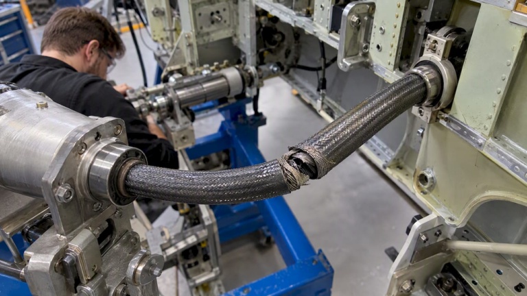
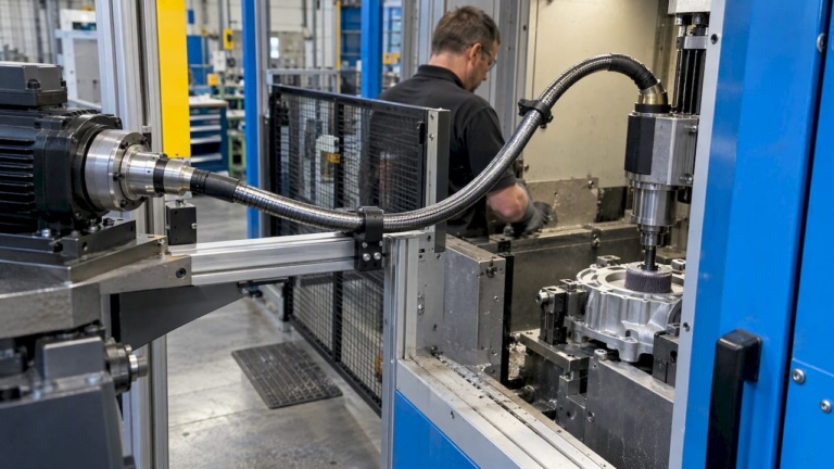
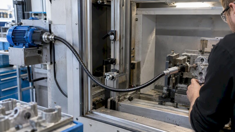
Biax-flexwellen designs flexible shafts and drive solutions specifically for applications where rigid shaft arrangements are impractical. In confined installation environments, including aerospace actuator systems, thrust reverser mechanisms, and industrial finishing equipment, a flexible shaft transmits torque reliably around bends and through tight spaces without requiring precise coaxial alignment between driver and driven components. This eliminates the alignment sensitivity that causes premature bearing and coupling failures in rigid drivetrains.
Biax-flexwellen supports machine builders with standard components, custom shaft configurations, and engineering guidance covering torque and RPM requirements, coupling interfaces, and protective sheath selection. Engineers working on deburring, grinding, polishing, or other finishing processes can review flexible shaft applications in industrial manufacturing, or contact Biax-flexwellen directly to discuss specific drive requirements. For a broader view of how flexible shafts affect machine design efficiency, the machine design efficiency resource provides detailed technical context.
FAQ
What is torque transmission in industrial machinery?
Torque transmission is the process of transferring rotational force from a power source to a driven component through mechanical elements such as gears, shafts, couplings, or fluid couplings. The goal is to deliver the required torque and speed at the output shaft with minimal energy loss.
What is the typical efficiency of an industrial gear stage?
A single industrial gear stage achieves 92% to 99% efficiency depending on gear type, lubrication condition, and load. Helical gears reach the upper end of this range, while worm gears at high ratios fall toward the lower end.
What causes most industrial gearbox failures?
Improper lubrication, overheating, and mechanical wear from overloading are the leading causes of unexpected gearbox downtime. Shaft misalignment and incorrect coupling selection are also primary contributors to accelerated wear and fatigue failure.
What gear ratio range gives the best efficiency in a single stage?
The optimal single-stage transmission ratio for industrial drives is between 5:1 and 25:1. Ratios outside this range either reduce efficiency significantly or require multi-stage gearbox arrangements to maintain acceptable power transfer.
When should a flexible shaft be used instead of a rigid shaft?
A flexible shaft is the correct choice when the driver and driven components cannot be aligned coaxially, when the installation path requires routing around obstacles, or when vibration isolation between the drive and the tool is required. Biax-flexwellen flexible shafts are designed for exactly these conditions in both industrial and aerospace applications.
Recommended
- Torque Transmission Guide for Mechanical Engineers
- Optimizing Torque Transmission Methods for Engineers
- Optimizing Torque Transmission: A How-To Guide for Engineers
- Optimize industrial torque transmission workflow: 5 key steps
Related Topics
Send your spec inquiry
Custom flexible shafts for your application — we quote within 1 working day.