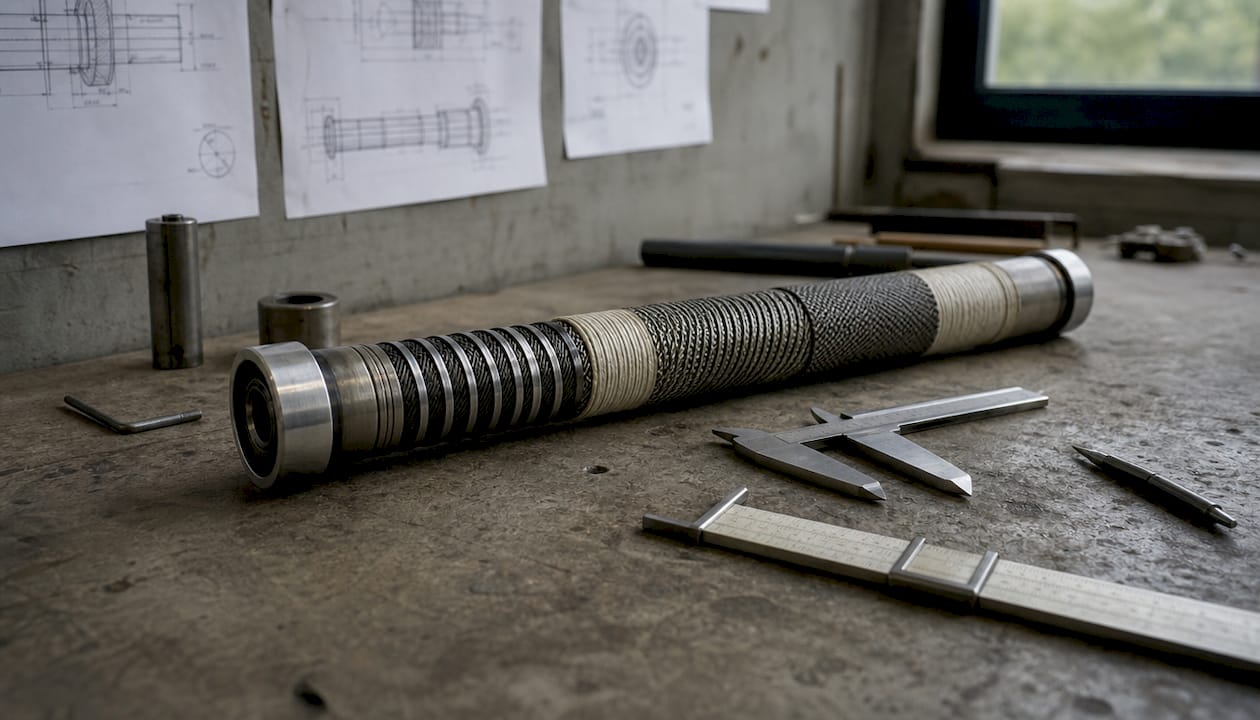
Custom Shaft Design for Engineers: A Technical Guide
6 July 2026TL;DR:
- Custom shaft design tailors rotating shafts to specific load, environmental, and operational needs beyond standard parts. Engineering this process improves performance, reduces failure risk, and ensures precise fit in demanding applications like aerospace and defense. Early use of FEA and careful manufacturing considerations prevent costly rework and optimize shaft reliability.
Custom shaft design is defined as the engineering process of creating rotating shafts precisely fitted to unique mechanical, environmental, and operational requirements that standard catalog parts cannot satisfy. Unlike stock shafts selected from a supplier’s SKU list, custom shafts are engineered for specific load, speed, fit, and environmental demands beyond standard parts. This distinction matters in aerospace, defense, and industrial manufacturing, where dimensional tolerances, fatigue life, and material properties must align with exact system requirements. Geometric Dimensioning and Tolerancing (GD&T) standards govern the critical dimensions. Biax-flexwellen applies this engineering discipline to flexible shaft and drive solutions for demanding industrial applications.
What is custom shaft design and how does it differ from stock shafts?
Custom shaft design is the process of producing a shaft from engineering drawings rather than selecting a pre-made component from a catalog. The difference is not cosmetic. A stock shaft is sized for general use, with standard diameters, common materials like 1045 carbon steel, and tolerances that fit a broad range of applications. A custom shaft is defined by its specific operating environment, and every geometric and material decision follows from that environment.
Custom shafts incorporate unique geometries like splines, keyways, and heat treatments tailored to machine requirements. These features are not available in standard catalog offerings at the required precision. A splined shaft for an aerospace actuator, for example, requires spline alignment within tight tolerances and a surface finish that prevents fretting wear over thousands of operating cycles.
The sectors that most consistently require custom shaft engineering include:
- Aerospace actuation systems: Flap and slat actuation, thrust reverser drives, and valve override mechanisms require shafts with certified materials, traceable heat treatment records, and runout tolerances that protect bearing life.
- Industrial finishing equipment: Deburring, grinding, and polishing systems, including flexible shaft drives like those produced by Biax-flexwellen, require shafts matched to specific torque and RPM envelopes.
- Defense and heavy machinery: Synchronization shafts in confined installation environments demand custom geometry to fit spatial constraints while transmitting defined torque loads.
- Medical and precision automation: Low-vibration, high-concentricity shafts are required where positional accuracy directly affects process quality.
Stock shafts fail in these contexts not because of poor manufacturing, but because they were never designed for the specific load path, coupling interface, or thermal environment of the application.
How to design a shaft: the core steps in the custom shaft design process
The shaft design process follows a defined engineering sequence. Skipping steps or reordering them produces designs that fail in manufacturing or in service.
-
Define torque and speed requirements. Power, torque, and rotational speed set the baseline. The relationship P = T × ω (power equals torque multiplied by angular velocity) establishes the minimum torsional capacity the shaft must carry. This calculation also identifies whether the shaft operates in a continuous or intermittent duty cycle, which affects material selection.
-
Build a free-body diagram. Mapping all forces via free-body diagrams is the critical early step in sizing shafts. The diagram documents the location, magnitude, and direction of every load acting on the shaft, including bending moments from gear or pulley forces, axial loads from thrust bearings, and torsional loads from the drive source. Missing a load at this stage leads to undersized cross-sections and expensive redesigns.
-
Select material based on strength and fatigue requirements. Common shaft materials include 4140 alloy steel for general high-strength applications, 17-4 PH stainless steel for corrosive environments, and titanium alloys for aerospace weight-critical designs. The endurance limit of the chosen material sets the fatigue life ceiling.
-
Size the shaft using combined stress criteria. The von Mises criterion and ASME shaft design equations combine bending and torsional stresses into an equivalent stress for sizing. This step produces the minimum shaft diameter at each critical cross-section.
-
Verify deflection and critical speed. Deflection analysis confirms that bearing and gear alignment stays within acceptable limits under load. Critical speed calculation identifies the rotational frequency at which the shaft resonates. Operating at or near critical speed causes rapid failure.
-
Apply GD&T to control critical dimensions. GD&T callouts for runout, concentricity, and perpendicularity translate the engineering intent into manufacturing instructions. Typical design controls runout under 0.01mm and spline alignment within 0.015mm for high-performance shafts. These tolerances are not arbitrary; they directly protect bearing life and reduce vibration.
-
Validate with Finite Element Analysis (FEA). FEA helps visualize stress distribution, identify weak spots, optimize weight, and prevent premature failures beyond what hand calculations reveal. FEA is required for any shaft where failure consequences are severe, including aerospace and defense applications.
Pro Tip: Complete the free-body diagram before opening CAD. Engineers who model geometry first and add loads later consistently miss load cases that only appear when the full force diagram is drawn on paper.
Design for manufacturing: avoiding common pitfalls in custom shaft engineering

Engineering a shaft that performs correctly on paper but cannot be manufactured to specification is a common and costly failure mode. Design for Manufacturing (DFM) principles address this gap between design intent and production reality.
DFM principles suggest avoiding overly tight tolerances and accounting for heat treatment distortion risks. Heat treatment changes shaft dimensions. A shaft ground to final diameter before case hardening will distort during the hardening cycle. The correct sequence is rough machine, heat treat, then finish grind to final tolerance. Reversing this sequence wastes the grinding operation and frequently scraps the part.
Key manufacturing considerations for custom shaft engineering:
- Turning and cylindrical grinding produce the primary shaft diameter and surface finish. Surface finish levels below 0.4 micrometers Ra are standard for reliable high-speed shafts, and grinding achieves this where turning alone cannot.
- Milling and broaching produce keyways and splines. Splined shafts need milling or broaching, which adds setup time and cost compared to plain turned shafts.
- Tool access is a frequent design oversight. Internal features, undercuts, and closely spaced shoulders can make certain operations impossible on standard CNC lathes. Designing with tool clearance in mind reduces manufacturing cost and lead time.
- Fillet radii at diameter transitions reduce stress concentration and improve fatigue resistance. A sharp shoulder is a stress riser. A generous fillet radius at the same location can double the fatigue life of that cross-section without adding material.
- Tolerance stacking across multiple features compounds error. Assigning tight tolerances to every dimension increases inspection cost and rejection rate. Reserve tight tolerances for features that directly affect function, such as bearing seats and coupling interfaces.
Pro Tip: When specifying surface finish, call out the Ra value and the measurement direction. Circumferential finish on a bearing journal behaves differently from axial finish on a thrust face. Ambiguous callouts produce parts that pass inspection but fail in service.
Simplifying CAD geometry does not always reduce costs. Careful geometric optimization like fillet radii and steps improves machinability and fatigue resistance. A shaft with well-placed fillets and chamfers is easier to machine and more reliable than a geometrically simple shaft with sharp transitions.
Mechanical design constraints: fatigue life, deflection, and critical speed
The three mechanical factors that most frequently determine shaft service life are fatigue, deflection, and critical speed. Static strength is rarely the governing criterion in rotating shaft applications.
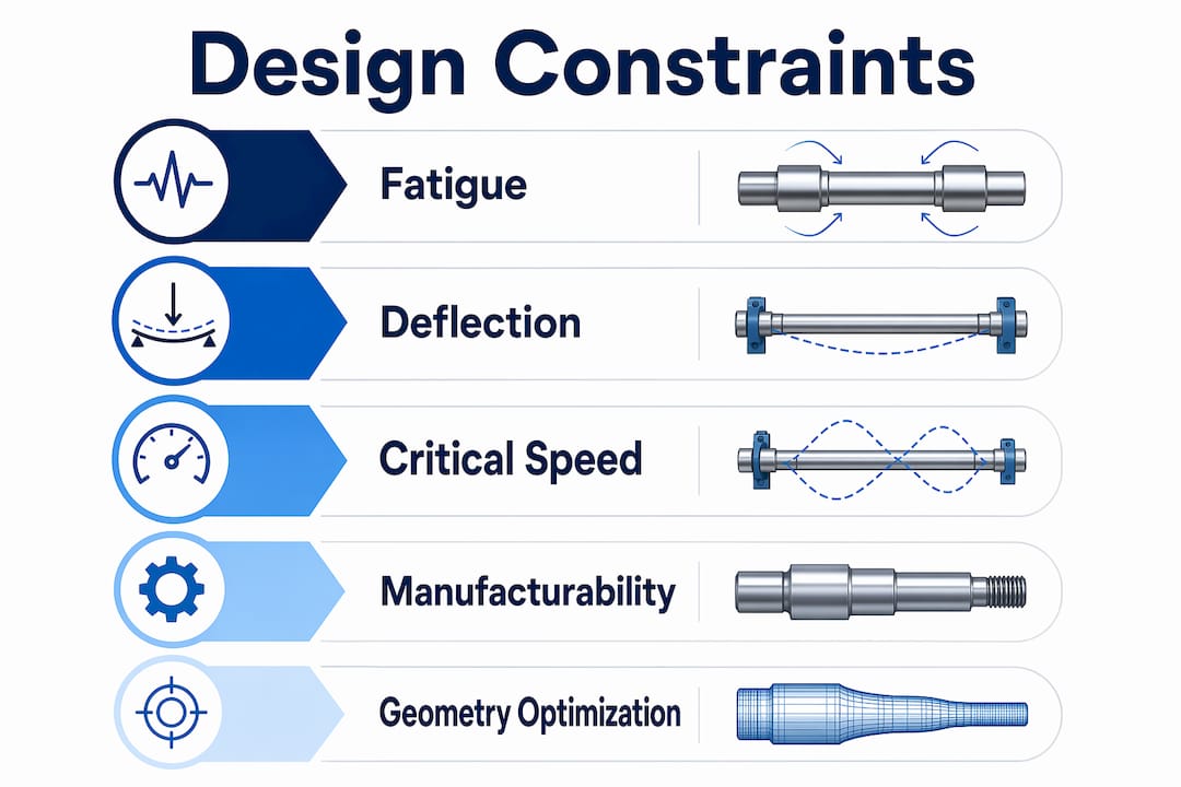
Shafts frequently fail after millions of load cycles rather than from a single peak load. Ignoring endurance limits results in premature shaft failure despite adequate static strength. This is the most common design error in shaft engineering. A shaft sized only for peak torque, without checking the endurance limit under cyclic loading, will fail in fatigue at a fraction of its calculated static capacity.
The table below summarizes the key mechanical design constraints and their engineering implications:
| Design Constraint | Governing Parameter | Failure Mode if Ignored | Engineering Control |
|---|---|---|---|
| Fatigue life | Endurance limit, stress concentration | Cracking at shoulders, keyways | Fillet radii, surface finish, material selection |
| Deflection | Length-to-diameter ratio, load magnitude | Bearing misalignment, gear wear | Shorter spans, larger diameters, intermediate supports |
| Critical speed | Natural frequency, shaft stiffness | Resonance, catastrophic failure | Stiffness increase, operating speed margin |
| Runout | Concentricity, bearing fit | Vibration, bearing fatigue | Tight GD&T callouts, precision grinding |
The length-to-diameter (L/D) ratio directly controls shaft stiffness. L/D ratios above 3:1 tend toward increased deflection and vibration during both machining and operation. Short, stiff shafts improve concentricity and surface finish by reducing deflection during manufacturing. When a long shaft is unavoidable, intermediate steady rests during machining and intermediate bearing supports in the final assembly reduce the effective unsupported span.
Critical speed is the rotational frequency at which the shaft’s natural frequency matches the excitation frequency. Operating at critical speed causes resonance and rapid structural failure. The design rule is to keep the maximum operating speed below 75–80% of the first critical speed, providing a margin against speed transients and manufacturing variation. For shaft design considerations in high-speed applications, this margin must be verified analytically, not estimated.
Deflection analysis protects the components mounted on the shaft. Excessive deflection at a gear mesh increases tooth load concentration. Excessive deflection at a bearing seat accelerates bearing fatigue. The allowable deflection is set by the gear or bearing manufacturer’s specification, not by a general rule of thumb.
Key Takeaways
Custom shaft design requires integrating fatigue life, deflection control, critical speed margins, and manufacturing constraints into a single coherent engineering solution from the first load analysis through final validation.
| Point | Details |
|---|---|
| Custom vs. stock shafts | Custom shafts are engineered per specific load, geometry, and tolerance requirements that catalog parts cannot meet. |
| Design process sequence | Define loads, build free-body diagrams, select material, size for combined stress, verify deflection and critical speed, then validate with FEA. |
| Fatigue governs service life | Shafts fail in fatigue after cyclic loading, not from peak static loads; endurance limits must be checked at every stress concentration. |
| DFM prevents costly errors | Sequencing heat treatment before finish grinding and specifying tolerances only on functional features reduces scrap and lead time. |
| L/D ratio controls stiffness | Shaft L/D ratios above 3:1 increase deflection and vibration risk; intermediate supports or larger diameters correct this. |
What working on shaft design projects has taught me about engineering priorities
Engineers entering custom shaft projects for the first time tend to focus on static strength. The shaft carries a known torque, so they size it for that torque and move on. The failures I have seen consistently come from what was not checked: the endurance limit at a keyway, the deflection at a gear mesh, the critical speed margin that disappeared when the operating range was extended during commissioning.
The shift that produces better shaft designs is treating fatigue as the primary design criterion and static strength as a secondary check. Industrial procurement should view custom shafts as engineered solutions aligned with system integration rather than commodity components. That framing changes how early the manufacturing partner gets involved. When the machinist reviews the drawing before the design is released, tool access problems and tolerance conflicts get resolved in hours instead of weeks.
The other lesson is that FEA is not a validation step to run at the end. FEA is critical for final shaft design verification, enabling weight optimization and identification of stress concentrations beyond standard calculation methods. Running FEA early, when geometry is still flexible, produces lighter and more reliable shafts than running it after the drawing is nearly complete. The hand calculations set the starting geometry. FEA refines it. Both steps are necessary.
For aerospace applications specifically, the confined installation environments and certification requirements make early collaboration with the manufacturing partner non-negotiable. A shaft that cannot be inspected to its GD&T callouts in the available fixturing is a shaft that will cause certification delays. That constraint belongs in the design conversation from day one.
— Uli
Biax-flexwellen engineering support for custom shaft applications
Biax-flexwellen supports machine builders and industrial manufacturers through the full custom shaft engineering process, from torque and RPM definition through coupling interface specification and final configuration. The engineering team works with standard components and fully custom configurations, including flexible shaft cores, protective sheaths, and actuation shaft assemblies for deburring, grinding, polishing, and finishing applications. For engineers working in confined or hard-to-reach installation environments, Biax-flexwellen’s flexible shaft applications cover the full range of industrial manufacturing demands. Technical inquiries, including torque requirements, RPM specifications, and coupling interface details, can be submitted directly through the Biax-flexwellen contact page for engineering review.
FAQ
What is custom shaft design in mechanical engineering?
Custom shaft design is the engineering process of creating a rotating shaft to exact load, speed, geometry, and tolerance specifications that standard catalog parts do not provide. It involves load analysis, material selection, stress calculations, and manufacturing controls specific to the application.
How does the shaft design process differ from selecting a stock shaft?
The shaft design process starts from operational requirements and produces a unique engineering drawing, while stock shaft selection starts from a catalog and accepts the nearest available size. Custom design controls tolerances, geometry, and material to match the system’s exact functional demands.
Why is fatigue life more critical than static strength in shaft design?
Shafts operate under cyclic loading, and fatigue failure occurs at stress levels well below the static yield strength. Endurance limits and stress concentrations at keyways, shoulders, and splines govern service life more than peak torque capacity.
What is the importance of the L/D ratio in custom shaft engineering?
The length-to-diameter ratio controls shaft stiffness and deflection. Ratios above 3:1 increase deflection and vibration during both machining and operation, which degrades surface finish, concentricity, and bearing life in the final assembly.
What role does FEA play in custom shaft fabrication?
FEA validates shaft designs beyond the limits of hand calculations by visualizing stress distribution, identifying stress concentrations, and enabling weight reduction. It is required for aerospace and high-consequence applications where failure analysis must be documented before production release.
Recommended
- Shaft Design Considerations for Engineers: A Technical Guide
- Custom Shaft Configurations Explained for Design Engineers
- What Is Custom Shaft Engineering for Industrial Design – BIAX Flexwellen
- Custom Flexible Shaft Configuration Guide for Engineers
Related Topics
Send your spec inquiry
Custom flexible shafts for your application — we quote within 1 working day.


