
Torque Transmission Guide for Mechanical Engineers
3 July 2026TL;DR:
- Torque transmission transfers rotational power using gears, belts, chains, or couplings, with efficiencies ranging from 92% to 99%. Accurate calculation of torque, considering operational conditions and misalignments, is essential for selecting proper components and ensuring system reliability. Proper maintenance, precise alignment, and appropriate lubrication significantly extend the lifespan of drive systems.
Torque transmission is the process of transferring rotational power from a driving shaft to a driven shaft through mechanical components such as gears, belts, chains, or couplings. This guide to torque transmission covers the core principles, calculation methods, component selection criteria, and maintenance practices that mechanical and aerospace design engineers rely on when specifying drive systems. Rotary power transmission systems operate with stage efficiencies between 92% and 99%, with frictional losses ranging from 1% to 15% per stage depending on gear type and lubrication. Understanding where those losses originate is the first step toward building a reliable, efficient drivetrain.
What is the guide to torque transmission and how does it work?
Torque transmission converts motor output into usable rotational force at the driven load. The governing relationship is straightforward: torque, speed, and power are linked, and changing one always affects the others.
Torque and speed are inversely proportional according to the equation T = (HP × 5,252) / RPM. Increasing speed reduces available torque at constant power, and reducing speed increases it. Every gearbox, belt drive, and chain drive exploits this relationship to match motor output to load requirements.
Two operational rules belong in every engineer’s working knowledge. First, power is conserved across an ideal transmission stage; only torque and speed change. Second, real stages introduce losses, so output power is always less than input power. Applying these rules from the start prevents undersized components and unexpected thermal loads.
Essential calculations for torque transmission design
Accurate torque calculation is the foundation of every component selection decision. Skipping this step or relying on shaft diameter alone leads to premature failure.
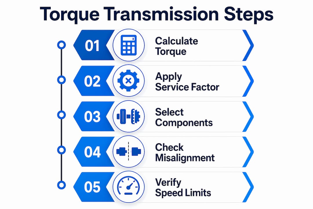
Core torque formula
The primary equation is:
T (lb-ft) = HP × 5,252 / RPM
Where T is output torque in pound-feet, HP is motor horsepower, and RPM is shaft speed. For SI units, substitute kilowatts and use T (Nm) = (kW × 9,549) / RPM.
Design torque and service factors
Design torque accounts for real operating conditions by multiplying calculated torque by an application-specific service factor (SF). Service factors vary by application type: centrifugal pumps and fans require SF 1.0–1.25, positive displacement pumps and mixers require SF 1.5–2.0, and high-shock applications such as compressors and crushers require SF 2.0–3.0. A crusher running at 50 HP and 200 RPM produces a calculated torque of 1,313 lb-ft. Applying SF 2.5 yields a design torque of 3,282 lb-ft, which is the value used for coupling and shaft selection.
Gear ratios and torque multiplication
The gear ratio determines how torque and speed scale between input and output shafts. A 5:1 ratio multiplies output torque by 5 and reduces output speed by the same factor. Optimal single-stage industrial ratios fall between 5:1 and 25:1. Exceeding this range in a single stage causes efficiency loss or requires disproportionately large and costly components.
Torque calculation workflow
- Determine motor rated HP and operating RPM.
- Calculate base torque using T = (HP × 5,252) / RPM.
- Identify the application type and assign the correct service factor.
- Multiply base torque by the service factor to obtain design torque.
- Select coupling, shaft, and gearing rated at or above design torque.
| Application Type | Service Factor | Example |
|---|---|---|
| Centrifugal pumps, fans | 1.0–1.25 | HVAC blowers, cooling towers |
| Positive displacement pumps, mixers | 1.5–2.0 | Concrete mixers, screw pumps |
| Compressors, crushers | 2.0–3.0 | Rock crushers, reciprocating compressors |
What are the main torque transmission methods in industry?
Mechanical engineers have four primary transmission methods available. Each carries distinct performance characteristics, maintenance requirements, and application constraints.

Gears
Gears deliver high power density with precise speed and phase control. They are the preferred choice when exact timing between shafts is required, such as in synchronization shafts for aerospace flap and slat actuation systems. Sliding between gear tooth surfaces is the primary source of torque loss and heat generation, making lubrication selection critical in high-speed or high-ratio applications.
Belts
Belt drives absorb shock loads and tolerate moderate shaft misalignment without transmitting vibration to connected equipment. V-belts and synchronous (timing) belts cover most industrial needs. Synchronous belts eliminate slip and suit applications requiring consistent speed ratios, while V-belts offer lower cost and easier field replacement.
Chains
Roller chain drives handle high torque at moderate speeds and perform well in contaminated or high-temperature environments where belts would degrade. Maintenance requirements are higher than belts because chains require periodic lubrication and tension adjustment. Chain drives are common in conveyor systems, agricultural machinery, and heavy manufacturing lines.
Couplings
Couplings connect two shafts and accommodate misalignment without transmitting bending loads to bearings. Disc couplings use thin metallic flexing elements and suit high-speed, high-torque applications with minimal maintenance. Modern disc coupling designs provide up to 26% greater torque capacity and 11% larger bore sizes compared to legacy designs. Chain couplings can handle torque ratings exceeding 1,500 Nm and tolerate misalignment up to 2 degrees, reducing maintenance costs by up to 30%. For a detailed breakdown of coupling roles in drivetrain design, the role of shaft couplings article covers selection criteria and efficiency factors in depth.
Pro Tip: When specifying couplings for confined aerospace installations, such as thrust reverser actuation or valve override systems, flexible shaft assemblies often replace rigid coupling chains entirely, eliminating alignment constraints in tight or curved routing paths.
| Coupling Type | Typical Torque Range | Misalignment Tolerance | Maintenance Level |
|---|---|---|---|
| Disc coupling | High (>1,500 Nm) | Angular, axial | Low |
| Chain coupling | Up to 1,500+ Nm | Up to 2° angular | Moderate |
| Jaw/spider coupling | Low to medium | Angular, parallel | Low |
| Gear coupling | Very high | Angular, parallel | Moderate to high |
How do you select and size torque transmission components reliably?
Component selection errors are the most common cause of premature drivetrain failure in industrial systems. Three principles govern reliable selection.
Size from torque, not shaft diameter
Coupling sizing must begin with torque calculation, not shaft diameter. Shaft diameter sets the minimum bore size, but the torque rating determines which coupling series is appropriate. Engineers who reverse this sequence routinely select couplings that fit the shaft but fail under load. The torque requirements workflow for machinery engineers provides a structured process for avoiding this error.
Manage misalignment
Misalignment is the leading cause of vibration, elevated bearing stress, and accelerated seal wear in rotating machinery. Angular, parallel, and axial misalignment each impose different load patterns on coupling elements and connected bearings. Maintaining shaft alignment and correctly applying service factors are the two most critical practices for avoiding premature component failure.
Key design practices for misalignment control:
- Specify shaft tolerances and hub fits to ISO H7/k6 or equivalent standards for interference fits.
- Use laser alignment tools during installation and after any thermal expansion event.
- Select coupling types rated for the expected misalignment type, not just the torque.
- Verify bearing housing alignment after foundation settling in new installations.
- Document baseline vibration signatures at commissioning for future comparison.
Account for speed-related limitations
Variable frequency drives (VFDs) suffer torque and cooling degradation below 30% of rated speed. For sustained low-speed, high-torque applications, mechanical gearboxes maintain full torque capacity and prevent motor thermal damage. Specifying a VFD alone for a crusher or extruder running at low speed is a design error with predictable consequences.
Pro Tip: Apply service factors before finalizing any coupling or gearbox selection. A pump that starts under load or experiences frequent reversals needs a higher SF than steady-state catalog values suggest. When in doubt, move up one SF tier.
Optimization and maintenance strategies for torque transmission systems
Reliable torque transmission depends as much on maintenance discipline as on initial design quality. Proactive inspection and lubrication schedules extend component life and reduce unplanned downtime.
Routine inspection priorities
- Check coupling element condition (spider inserts, disc packs, chain links) at every scheduled maintenance interval.
- Verify shaft alignment using laser tools after thermal cycling, foundation work, or bearing replacement.
- Inspect gear tooth surfaces for pitting, spalling, or abnormal wear patterns that indicate lubrication failure.
- Monitor operating temperature at gearbox housings and coupling guards as an early indicator of friction increase.
- Review vibration data against commissioning baselines to detect developing imbalance or misalignment.
Lubrication and gear efficiency
Sliding friction between gear teeth is the primary source of heat and efficiency loss in gear trains, not simple mechanical friction. This distinction matters because it directs lubrication selection toward oils with high film strength and anti-wear additives, not just viscosity. High-speed helical gears and worm gears are particularly sensitive to lubricant film breakdown.
Proactive maintenance schedules for industrial torque transmission components consistently show that lubrication interval adherence is the single highest-return maintenance activity in rotating machinery.
Coupling innovations in 2026 are closing the gap between high-torque capacity and low maintenance burden. Disc coupling designs with up to 26% greater torque density reduce the need for oversizing, while condition monitoring integration allows maintenance teams to act on data rather than fixed schedules. Engineers who adopt these technologies early reduce both capital cost and lifecycle maintenance spend.
Monitoring techniques
Vibration analysis, thermal imaging, and oil particle counting each detect different failure modes. Vibration analysis identifies imbalance and misalignment. Thermal imaging locates friction hotspots in gearboxes and couplings. Oil particle counting detects gear tooth wear before visible damage appears. Using all three in combination gives the most complete picture of system health.
Key Takeaways
Reliable torque transmission requires accurate design torque calculation, correct service factor application, and disciplined alignment and maintenance practices throughout the system’s service life.
| Point | Details |
|---|---|
| Calculate design torque first | Multiply base torque by the application service factor before selecting any component. |
| Size couplings by torque rating | Shaft diameter sets bore size only; torque rating determines the correct coupling series. |
| Control misalignment at installation | Use laser alignment tools and verify fits to ISO H7/k6 or equivalent standards. |
| Match drive type to speed range | Use mechanical gearboxes for sustained low-speed, high-torque loads where VFDs degrade below 30% speed. |
| Prioritize lubrication discipline | Sliding gear tooth friction is the primary efficiency loss source; correct lubricant selection is not optional. |
What I’ve learned from years of torque transmission design decisions
The calculation side of torque transmission is well documented. The harder lessons come from field experience, and most of them involve service factors and misalignment.
Engineers frequently apply service factors from catalog tables without examining the actual duty cycle. A mixer that starts under full load three times per shift is not the same application as one that starts unloaded. The catalog SF for mixers covers the average case. The actual application may need a factor at the top of the range or beyond it. I have seen coupling failures traced directly to this gap between catalog assumption and real operating conditions.
Misalignment is the other persistent problem. Laser alignment at installation is now standard practice in most facilities, but thermal growth after startup is often ignored. A gearbox that aligns perfectly at ambient temperature may be significantly misaligned at operating temperature. Specifying flexible couplings with adequate misalignment capacity for the thermal delta is not over-engineering. It is the correct design.
The integration of compact flexible shaft assemblies in confined installations, particularly in aerospace actuation systems, resolves both problems simultaneously. A flexible shaft routes around obstacles without rigid alignment constraints and inherently accommodates relative motion between connected components. For thrust reverser systems, valve override mechanisms, and synchronization shafts in tight airframe spaces, this approach eliminates the alignment management problem entirely.
The broader lesson is that torque transmission selection is always a trade-off between mechanical complexity, maintenance requirements, and alignment precision. The engineers who make the best decisions are the ones who quantify all three factors before committing to a design, not after the first failure.
— Uli
Biax-flexwellen drive solutions for industrial torque transmission
Biax-flexwellen designs and manufactures flexible shaft assemblies and drive solutions for industrial applications where rigid shaft arrangements are impractical. The product range covers deburring, grinding, polishing, and finishing processes, as well as actuation and synchronization functions in confined or curved routing environments. Standard configurations address common torque and RPM requirements, while custom configurations accommodate specific coupling interfaces, protective sheath designs, and shaft geometries. Engineers working on machine builds or system upgrades can review the full range of flexible shaft applications for industrial manufacturing, or consult the rigid vs. flexible shaft selection guide to determine the appropriate drive architecture. For project-specific requirements, contact Biax-flexwellen directly via the engineering inquiry form.
FAQ
What is the basic formula for calculating torque in a transmission system?
Torque in pound-feet equals horsepower multiplied by 5,252, divided by shaft speed in RPM. For SI units, use T (Nm) = (kW × 9,549) / RPM.
Why must coupling selection start with torque, not shaft diameter?
Shaft diameter determines the minimum bore size only. The torque rating governs which coupling series is structurally adequate. Selecting by bore size alone produces couplings that fit but fail under load.
What service factor applies to a crusher or compressor application?
High-shock applications such as crushers and reciprocating compressors require a service factor of 2.0–3.0 applied to the calculated torque before component selection.
How does misalignment affect torque transmission system life?
Angular, parallel, and axial misalignment impose cyclic bending loads on coupling elements and bearings, accelerating wear and reducing service life. Laser alignment at installation and after thermal cycling is the standard mitigation.
When should a mechanical gearbox be used instead of a VFD?
A mechanical gearbox is required for sustained low-speed, high-torque operation. VFDs lose torque capacity and cooling effectiveness below 30% of rated speed, making them unsuitable as the sole speed control method in heavy-duty low-speed applications.
Recommended
- Optimizing Torque Transmission: A How-To Guide for Engineers
- Torque Requirements Workflow for Machinery Engineers
- Defining Rotational Power Transmission for Engineers – BIAX Flexwellen
- Optimizing Torque Transmission Methods for Engineers
Related Topics
Send your spec inquiry
Custom flexible shafts for your application — we quote within 1 working day.


