
Edge Finishing for Aerospace Engineers: A 2026 Guide
5 August 2026Edge finishing is the industrial process of removing burrs, controlling edge radii, and producing the required surface integrity on metal and composite part edges to meet fatigue, fit, and coating requirements. For critical structural components, aerospace standards mandate documented edge-radius consistency within a narrow range to prevent stress concentration and protect fatigue life. Three considerations govern every specification decision: edge-radius consistency (typically called out as a tolerance band on the drawing), surface integrity (residual stress state and subsurface damage), and tooling accessibility for internal or undercut features. Blue-light 3D scanning and drive solutions such as Biax-flexwellen flexible shafts are the practical answers to the last two of those constraints.
Table of Contents
- What are the main edge-finishing methods engineers use?
- How do you choose the right edge-finishing process for aerospace parts?
- How does material choice affect the edge-finishing process?
- How do you finish internal and undercut features in aerospace assemblies?
- How should edge finish be specified on engineering drawings?
- Which inspection methods reduce cost and variation in edge finishing?
- When does automating edge finishing deliver a positive ROI?
- What is PPSF and why does it matter for fatigue-critical rotating parts?
- Key Takeaways
- The case for specifying access early, not retrofitting it
- Engineering support for confined-feature finishing
- Useful sources and standards for further reading
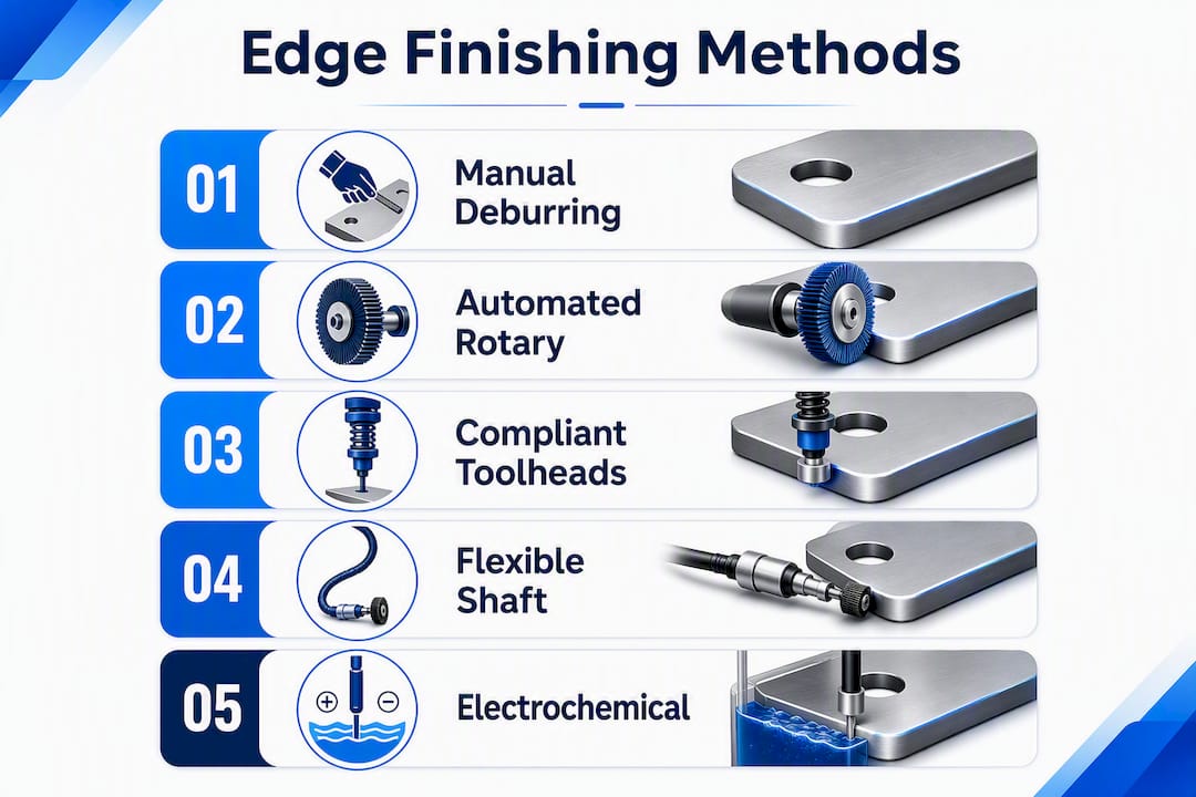
What are the main edge-finishing methods engineers use?
Each process family targets a different removal regime and part geometry. Selecting the wrong one wastes cycle time or damages surface integrity.
- Mechanical rotary/hand tools (carbide burrs, die grinders): fast stock removal, Ra typically varies within a range that depends on operator consistency. Best for prototype or low-volume rework.
- Flexible abrasive hones and brushes: effective for hole-edge rounding and cross-hole intersections; limited material removal on heavy burrs in tough superalloys, so use after chamfering.
- Vibratory/mass finishing: high-throughput batch process; optimized media and parameters can achieve Ra values approaching 2–3 µin on turbine components, though extended cycles of 10–24 hours are common depending on start condition.
- Abrasive flow machining (AFM): forces abrasive media through internal passages; reaches bores and cross-holes inaccessible to rotary tools; cycle times are long and tooling costs are high.
- Electropolishing: removes micro-peaks electrochemically; excellent for stainless and nickel alloys; not suitable for titanium or CFRP.
- Laser deburring: non-contact, precise; limited to thin burrs and line-of-sight features; capital cost is high.
- Tumbling/centrifugal barrel finishing: similar to vibratory but higher energy; shorter cycles for equivalent Ra; media selection is critical for thin-wall parts.
Automated compliant toolheads replace manual rotary tools when volume, consistency, or documentation requirements exceed what hand finishing can deliver. Research confirms that contact stress, not constant tool force, determines finish quality; compliant toolheads with pressure and extension sensing maintain that stress across varying geometry.
How do you choose the right edge-finishing process for aerospace parts?
A structured selection sequence prevents costly process changes late in the program.
- Define the functional requirement. Fatigue-critical rotating parts need radius control and compressive residual stress. Flow-path components need Ra targets. Assembly interfaces need burr-free edges and dimensional conformance.
- Quantify the edge radius, tolerance, and Ra target. Translate functional requirements into drawing callouts before selecting a process. A radius callout without a tolerance is not a specification.
- Evaluate accessibility. Internal cross-holes, deep bores, and undercuts eliminate several process families immediately. Accessibility is the dominant engineering challenge in aerospace deburring, often more limiting than material hardness.
- Match media and tooling to material. Hard alloys and composites require tailored abrasive sequences; conventional media wears rapidly on nickel superalloys and CFRP.
- Define the inspection plan and sampling frequency. Critical parts require documented in-process verification, not end-of-line sampling alone.
- Scale the process to volume. Prototype and low-rate production justify manual or semi-automated finishing. Higher volumes and tighter variation budgets shift the decision toward in-line robotic finishing or mass finishing with flexible drive systems for confined features.
When variation reduction and throughput targets cannot be met manually, the next step is a compliant robotic toolhead with pre-process geometry mapping. Mass finishing becomes viable when part geometry permits batch loading without mutual damage.
How does material choice affect the edge-finishing process?
Material properties determine abrasive selection, allowable contact stress, and whether a given process family is viable at all.
| Material | Key challenges | Recommended process families | What to avoid |
|---|---|---|---|
| Aluminum alloys | Soft, prone to smearing; burrs tear rather than shear | Flexible brush hones, vibratory with plastic media, light mechanical | Aggressive ceramic media; electropolish (alloy-dependent) |
| Titanium (Ti-6Al-4V) | Work-hardening, galling, heat sensitivity | Polyester media in vibratory, flexible abrasive hones, AFM for internal passages | High-speed dry mechanical; conventional steel media |
| Inconel 718 / nickel superalloys | High hardness, tough burrs, residual stress sensitivity | Ceramic or silicon carbide abrasives in flexible configurations, AFM, electropolish | Flexible brushes alone for heavy burrs; media that induces tensile residual stress |
| CFRP / multilayer composites | Fiber pullout, delamination, abrasive wear on tooling | Specialized diamond-coated tools, low-force flexible hones, defuzzing brushes | Vibratory with hard ceramic media; high-contact-force mechanical |
Advanced materials including nickel superalloys, titanium, and CFRP require tailored abrasive sequences because conventional abrasives wear rapidly and may not achieve the Ra or residual-stress targets required. For Inconel and similar alloys, grit progression from coarse ceramic to fine silicon carbide, followed by electropolishing where geometry permits, is a common sequence. AFM is most appropriate when internal passages must be finished uniformly and no rotary tool can reach the feature.
CFRP requires the lowest contact force of any aerospace material. Fiber pullout and delamination are irreversible; a flexible hone with diamond abrasive at controlled feed rate is the standard approach for hole-edge defuzzing.
How do you finish internal and undercut features in aerospace assemblies?
Accessibility constraints eliminate most standard tooling before the first cut. A structured approach to confined-feature finishing prevents late-stage process failures.
- Internal cross-holes and intersecting passages: flexible abrasive hones or brush tools driven through the bore; automated deburring of cross-hole intersections in aerospace engine components is a documented application for modular flexible-drive systems.
- Deep bores and undercuts: AFM or flexible shaft-driven rotary tools; rigid spindles cannot follow the geometry.
- Tight-bore intersections in actuator housings: flexible shafts transmit torque around bends and through confined envelopes where a straight drive cannot reach.
Flexible-drive investment is a differentiator for in-house capability versus outsourcing to electrochemical or AFM processes. Biax-flexwellen flexible shafts enable access for precision deburring in exactly these confined installations, transmitting the torque and RPM a finishing tool requires without a direct line-of-sight drive path.
When integrating flexible shafts into a CNC or robot cell, the toolhead must be mechanically compliant. Controlling contact stress rather than raw force is what produces consistent edge geometry across part-to-part variation.
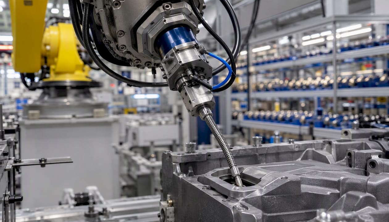
Pro Tip: Run blue-light 3D scanning or automated probe routines before automating any finishing operation. Relying on nominal CAD geometry causes over-cutting where manufacturing deviations exist; real-world geometry mapping feeds adaptive toolpaths that protect part integrity.
How should edge finish be specified on engineering drawings?
Vague callouts produce inconsistent parts. Prescriptive language on the drawing and in the purchase order is the only reliable control.
Edge radius callouts: use the format R0.5 ±0.05 mm on the feature, with a general note defining the default tolerance for unspecified edges (e.g., “All edges R0.2–0.5 unless otherwise noted”). Chamfer notation (e.g., 0.3×45°) is acceptable for non-fatigue-critical interfaces but should not substitute for radius callouts on fatigue-loaded features.
Surface roughness: specify Ra in µin or µm with the applicable measurement cutoff length. Critical flow-path surfaces often require Ra ≤ 32 µin (0.8 µm); bearing interfaces may require Ra ≤ 16 µin (0.4 µm).
Procurement clauses: require the supplier to submit a process recipe (media type, machine parameters, cycle time), in-process scan reports, and residual stress verification for fatigue-critical parts. Include change-control language that requires re-qualification if any process parameter changes.
Accessibility notes: if the part has features that require specialized tooling (flexible shaft drives, AFM), state that in the purchase order and confirm the supplier’s capability before award.
Which inspection methods reduce cost and variation in edge finishing?
Metrology integrated into the finishing workflow catches variation before it becomes scrap.
- Blue-light 3D scanning: full-surface geometry capture; measures edge radius, form deviation, and burr presence across the whole part; typical point density supports statistical sampling for aerospace acceptance.
- Automated touch-probe routines (CNC in-process): fast, repeatable radius and profile verification at defined feature locations; requires calibrated probe geometry for small radii.
- Contact profilometry: measures Ra and Rz at defined surface locations; standard for surface-roughness acceptance.
- Optical inspection systems: burr detection and edge-break verification on flat or accessible features; less effective for internal geometry.
Automated in-process verification reduces unit cost and variability compared to end-of-line manual inspection. The workflow sequence is: pre-process geometry mapping → adaptive toolpath generation → in-process verification at defined intervals → final acceptance sampling. Calibrating small tool radii inside the CNC using laser or touch-probe routines maintains profile consistency across a production run.
When does automating edge finishing deliver a positive ROI?
The decision to automate depends on geometry complexity, batch size, and documentation burden, not throughput alone.
Key cost drivers: part geometry complexity (number of features, accessibility), material abrasiveness (hard alloys consume tooling faster), batch size, required documentation intensity, and outsourcing lead time. Manual spot finishing on a simple aluminum bracket costs a fraction of what robotic finishing of a titanium blisk costs, but the variation and documentation gap widens with part criticality.
Automation thresholds: when part-to-part variation in manual finishing exceeds the drawing tolerance, or when documentation requirements cannot be met consistently by hand, automation pays. Flexible-drive robotic cells are justified when internal features preclude standard end-effectors and outsourcing adds unacceptable lead time.
Typical cycle-time ranges by process family in aerospace finishing: manual spot finishing runs 5–30 minutes per part depending on feature count; robotic compliant finishing runs 3–15 minutes per part with consistent output; vibratory mass finishing runs 2–24 hours per batch; AFM runs 10–60 minutes per part depending on passage complexity. Unit cost per part drops with volume in automated and mass-finishing processes but remains relatively flat in manual operations.
What is PPSF and why does it matter for fatigue-critical rotating parts?
Precision and Performance Synergy Finishing (PPSF) is a sequenced process combining polishing, shot peening, and mass finishing steps to improve surface integrity and fatigue life on engine-critical components such as blisks and gears. PPSF is gaining adoption for engine-critical parts because it targets surface integrity and fatigue-life improvement rather than simple material removal.
The process sequence typically moves from coarse material removal and edge rounding, through shot peening to induce compressive residual stress, to fine polishing that reduces Ra and removes peening-induced surface roughness. The result is a part with a smooth, compressively stressed surface that resists fatigue crack initiation.
PPSF fits in the process chain after final machining and before coating or assembly. Specify it when the part is a rotating fatigue-critical component and the design life calculation depends on surface integrity, not just dimensional conformance. For localized features on otherwise simple parts, automated compliant finishing with a controlled contact-stress strategy achieves similar surface integrity at lower process cost. Media selection and sequence order are the primary variables; changing either requires re-qualification.
Key Takeaways
Edge finishing for aerospace components requires documented radius control, material-matched abrasive selection, and in-process metrology to meet fatigue and assembly requirements consistently.
| Point | Details |
|---|---|
| Define before specifying | Translate functional requirements (fatigue, flow, assembly) into radius tolerances and Ra targets before selecting a process family. |
| Material drives media choice | Nickel superalloys need ceramic or SiC abrasives; titanium needs polyester media or AFM; CFRP needs low-force diamond tooling to prevent delamination. |
| Accessibility limits process options | Internal cross-holes and undercuts eliminate most standard tooling; flexible shaft drives and AFM are the primary solutions for confined features. |
| Automate when variation exceeds tolerance | Robotic compliant finishing with contact-stress control outperforms manual methods when part-to-part variation or documentation requirements cannot be met by hand. |
| Biax-flexwellen for confined-feature access | Biax-flexwellen flexible shafts transmit torque to finishing tools in tight bores, undercuts, and actuator housings where rigid drives cannot reach. |
The case for specifying access early, not retrofitting it
The most expensive edge-finishing problems are the ones discovered after the machining cell is built. A cross-hole intersection that was never modeled as a finishing feature, a bore too deep for any standard hone, an undercut that no end-effector can reach — these are not finishing problems. They are design problems that finishing is asked to solve.
The conventional approach is to finalize part geometry, release the drawing, and then ask the finishing engineer to figure it out. That sequence consistently produces late-stage process development, outsourcing to AFM or electrochemical shops, and documentation gaps that delay first article inspection. The better sequence is to flag accessibility constraints during the design review, specify the finishing method alongside the tolerance, and select drive solutions before the cell is laid out.
Flexible shaft technology exists precisely because rigid drives cannot reach every feature a designer can create. The engineering question is not whether a flexible shaft can transmit the required torque and RPM — that is a solvable specification problem. The question is whether the finishing requirement was identified early enough to integrate the drive solution cleanly. When it is, the result is a finishing cell that reaches every feature, documents every operation, and does not require a manual rework station at the end of the line.
Engineering support for confined-feature finishing
When part geometry requires finishing in bores, cross-holes, or actuator housings that standard tooling cannot reach, Biax-flexwellen provides flexible shaft drive solutions sized to the torque, RPM, length, and coupling requirements of the application. The product range covers standard configurations and custom designs for integration into CNC machining centers, robotic finishing cells, and manual drive stations.
Engineers specifying deburring or polishing for internal passages, valve override systems, or synchronization shaft housings can submit technical parameters directly to the Biax-flexwellen engineering team for configuration guidance. Flexible shaft applications for industrial manufacturing include cross-hole deburring, deep-bore finishing, and confined-space polishing across aluminum, titanium, and nickel alloy components. For a direct engineering inquiry, contact Biax-flexwellen via the engineering contact page.
Useful sources and standards for further reading
- Automated component deburring in aerospace — Aerospace Manufacturing & Design: practical coverage of cross-hole deburring, accessibility challenges, and honing tool integration in aerospace machining centers.
- Automation of the edge deburring process and analysis of selected parameters — MDPI Applied Sciences: process data on forces and moments during automated deburring of low-pressure turbine blades; useful for robotics cell design.
- Flexible abrasive tools for deburring and finishing of holes in superalloys — MDPI Manufacturing, 2019: experimental data on flexible brush and hone performance on Inconel 718; covers material removal limits and Ra outcomes.
- Experimental investigation of surface integrity during abrasive edge profiling of nickel-based alloy — ScienceDirect: first-of-kind study on Inconel 718 edge profiling; covers residual stress, Ra, and surface integrity outcomes.
- Advanced workpiece materials and finishing solutions — SME: industry primer on media selection, process development for hard alloys and composites, and mass finishing cycle-time data.
- PPSF research for aerospace engine components — Chinese Journal of Aeronautics, 2024: PPSF concept, sequencing, and fatigue-life improvement data for blisks and gears.
- Crosshole deburring of complex aerospace parts — Aerospace Magazine: application-level coverage of cross-hole deburring strategies and accessibility solutions in engine component manufacturing.
Recommended
- Machining Components Terminology: A Practical Engineer’s Guide
- Machining in Hard-to-Reach Spaces: A Guide for Engineers – BIAX Flexwellen
- Flexible Shafts in Manufacturing: Precision & 2026 Insights – BIAX Flexwellen
- The Role of Engineering Guidance in Manufacturing – BIAX Flexwellen
Related Topics
Send your spec inquiry
Custom flexible shafts for your application — we quote within 1 working day.


