Flexible drive solutions for efficient industrial design
24 April 2026TL;DR:
- Flexible drive solutions handle misalignments up to 180 degrees, increasing design flexibility.
- They transmit torque through complex paths, absorbing vibration and reducing maintenance needs.
- Proper selection ensures longevity by matching torque, speed, and bend radius to application demands.
Flexible drive solutions for efficient industrial design
Transmitting rotary power through confined spaces, around obstacles, or across misaligned axes has long been one of the more stubborn challenges in machine design. Rigid shafts, belts, and gearboxes impose strict geometric constraints that push up complexity, increase component counts, and raise maintenance costs. Flexible drive solutions cut through many of these limitations, offering design engineers and production engineers a reliable way to route torque where it is needed without sacrificing efficiency or durability. This article covers the mechanics, key benefits, selection criteria, and real-world applications of flexible drive technology in demanding industrial processes such as deburring, grinding, and polishing.
Table of Contents
- Understanding flexible drive solutions
- Major benefits of flexible drive solutions for engineers
- Selecting the right flexible drive for your application
- Real-world applications: Deburring, grinding, and polishing
- Why flexibility is shaping the future of industrial drive design
- Explore flexible drive solutions for your engineering challenges
- Frequently asked questions
Key Takeaways
| Point | Details |
|---|---|
| Handles misalignment | Flexible drive solutions transmit power reliably through bends and tight spaces without sacrificing efficiency. |
| Boosts system efficiency | High-quality flexible shafts achieve efficiency ratings over 90% while absorbing vibration and shock. |
| Enables compact design | Engineers use flexible drives to create smaller, more versatile machines for challenging applications. |
| Ideal for tough tasks | Flexible drive solutions excel in demanding processes like deburring, grinding, and polishing. |
Understanding flexible drive solutions
A flexible drive solution transmits rotary motion and torque from a motor to a tool or driven component through a shaft that can bend, curve, and navigate complex routing paths. Unlike a rigid shaft constrained to a single axis, a flexible shaft conforms to the geometry of the machine and the workspace.
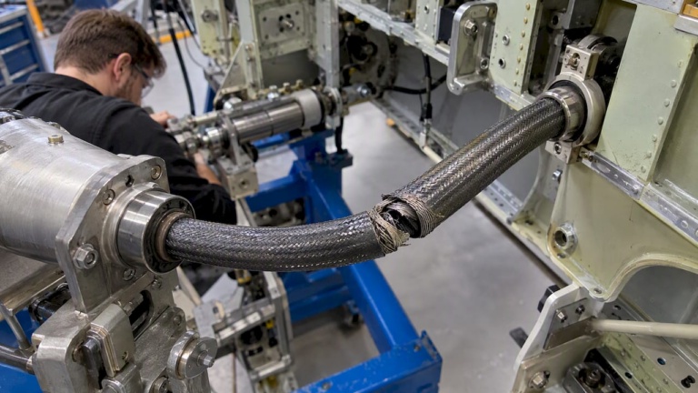
The core construction uses a wound wire or layered composite core, typically manufactured from high-tensile steel or specialized alloys, wrapped in successive helical layers. Each layer alternates winding direction to balance torsional forces and prevent uncoiling under load. The outer protective sheath, often a steel-reinforced polymer conduit, constrains the shaft and defines the bend radius. Together, the core and sheath create a drive element that is both strong and adaptable.
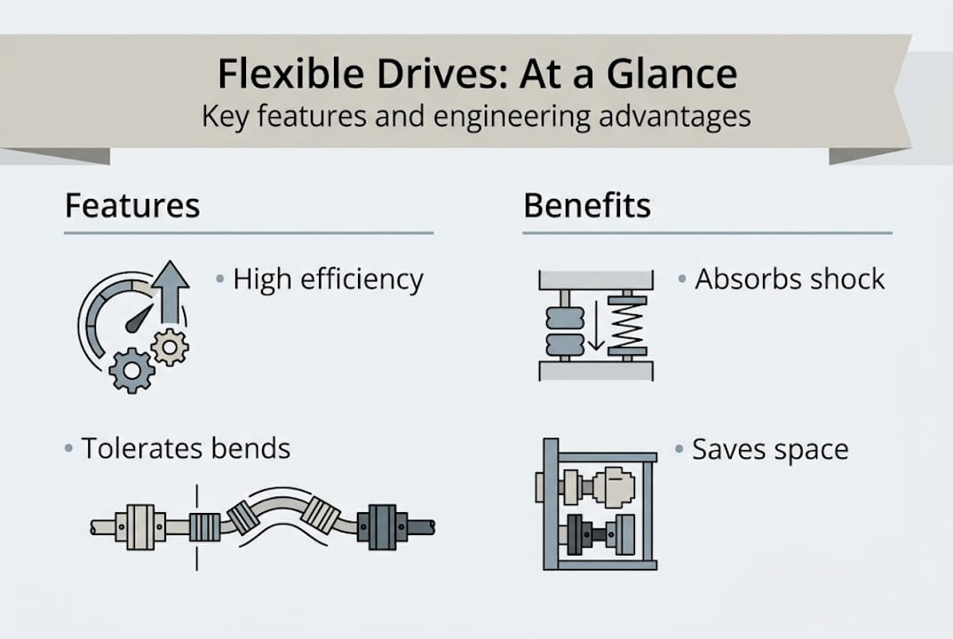
Flexible shafts transmit rotary motion and torque through bends and complex paths, absorb vibration and shock, enable compact machinery designs, and deliver efficiency ratings exceeding 90% while handling up to 180 degrees of misalignment. That combination is difficult to match with rigid components.
The mechanics involve a motor driving rotary tools via a flexible shaft constructed from wound wire or elastic materials, balancing flexibility with strength using high-tensile steel or alloys. This balance is critical: too much flexibility reduces torque capacity; too little defeats the purpose of the flexible element.
Flexible drives appear across a wide range of environments. Review the flexible shaft benefits for a breakdown of application categories. Typical environments include:
- Deburring and edge finishing on complex castings and machined parts
- Grinding and material removal in confined bores or on curved surfaces
- Polishing of contoured components in automotive and aerospace finishing lines
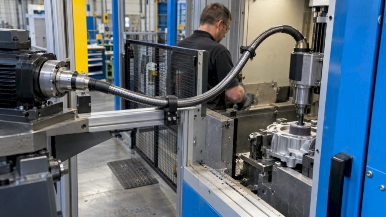
- Robotics and automation where the end-effector must navigate tight paths
- Medical and dental equipment requiring compact, precise rotary drive
| Property | Typical range |
|---|---|
| Efficiency | >90% |
| Misalignment tolerance | Up to 180° |
| Shaft outer diameter | 4 mm to 35 mm |
| Core material | High-tensile steel, alloy steel |
| Sheath material | Steel-reinforced polymer |
| Operating temperature | Up to 120°C (standard grades) |
For guidance on how these drives influence broader design architecture, see machine design efficiency.
Pro Tip: Never exceed the manufacturer-specified minimum bend radius. Operating a flexible shaft at too sharp a bend angle generates excessive internal friction, rapidly increases heat, and shortens service life. If the application geometry demands a tight curve, select a smaller-diameter shaft optimized for that radius rather than forcing a larger-diameter unit to conform.
Major benefits of flexible drive solutions for engineers
With mechanics and material context in place, the specific engineering advantages of flexible drive solutions become clear. These advantages are most impactful when compared directly against the alternatives: rigid couplings, universal joints, and belt or chain drives.
Rigid shaft systems require precise collinear alignment between the motor and the driven tool. Any deviation produces vibration, bearing wear, and premature failure. Universal joints tolerate angular misalignment but introduce velocity fluctuations at the driven end, which degrade surface finish in grinding and polishing. Belt drives handle misalignment and absorb some vibration, but they require tensioning hardware, guards, and regular inspection of belt condition.
Flexible drive shafts address all three problems simultaneously. Efficiency ratings exceeding 90% with the ability to handle up to 180 degrees of misalignment make these drives competitive with rigid systems on power throughput while eliminating the alignment burden entirely. The connected machinery benefits of reduced downtime and simpler maintenance schedules reinforce this value proposition at the system level.
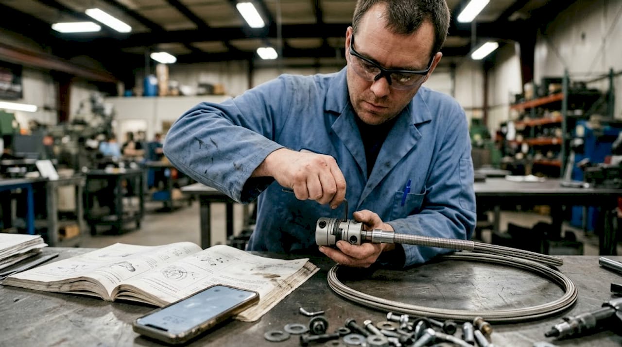
Flexible shafts also absorb shock and vibration passively. In hand-held grinding tools and machine-mounted deburring spindles, the shaft core acts as a compliance element between the motor and the tool. Transient overloads and surface irregularities that would spike bearing loads in a rigid system are attenuated before they reach the motor. This reduces motor maintenance intervals and extends bearing life in the driven spindle.
| Drive type | Compactness | Maintenance | Vibration tolerance | Misalignment range | Reliability in tight spaces |
|---|---|---|---|---|---|
| Flexible shaft | High | Low | Excellent | Up to 180° | Excellent |
| Rigid shaft | Low | Medium | Poor | Near zero | Poor |
| Belt drive | Medium | High | Good | Limited | Moderate |
The advantages are most noticeable in these scenarios:
- Tight-space assembly where motor and tool cannot share the same axis
- Robot arm end-effectors requiring torque delivery through articulated joints
- High-vibration tools where operator fatigue and equipment wear are concerns
- Multi-spindle machines where one motor drives several tools through branched flexible shafts
- Applications requiring frequent tool changes without realignment procedures
Explore the full range of drive systems efficiency advantages when evaluating system-level trade-offs. For a direct look at product configurations, the compact efficiency solutions overview provides specification-level detail.
Pro Tip: For trouble-free maintenance, standardize on a single shaft series across similar machines in your facility. Consistent shaft diameter, coupling interface, and sheath type reduce spare parts inventory and simplify technician training. When one shaft design covers 80% of your applications, swaps become routine rather than engineering exercises.
Selecting the right flexible drive for your application
Understanding the benefits, the next step is choosing the flexible drive that matches your specific production needs. Selection is a structured process; skipping steps leads to under-specification, early failure, or unnecessary cost.
Follow this framework:
- Assess required torque. Calculate the continuous torque demand at the driven tool, including a service factor for intermittent peak loads. Do not select based on motor output alone; shaft rating must cover the full torque path.
- Define the operating speed range. Flexible shafts are speed-sensitive. Critical speed limits depend on shaft diameter, free length, and bend configuration. Confirm that the rated rpm at your bend radius exceeds your maximum operating speed with an adequate margin.
- Determine minimum bend radius. Map the physical routing of the shaft inside the machine. Identify the tightest curve the shaft must navigate. Match this radius to the shaft manufacturer’s minimum bend radius table for the selected diameter.
- Evaluate the operating environment. Consider temperature, coolant exposure, contamination by metal chips or abrasives, and humidity. Specify sheath and core materials accordingly. Food-grade or stainless configurations exist for clean-room and wet environments.
- Account for vibration and shock loads. If the driven tool produces impact loads (as in chiseling or intermittent contact grinding), select a shaft with an energy-absorbing core and confirm that the sheath anchoring prevents relative movement between the shaft and the conduit at the ends.
- Choose coupling interfaces. Motor-end and tool-end couplings must mate with existing components. Standard square, hexagonal, and proprietary interfaces are common. Custom couplings are available from suppliers who specialize in engineered configurations.
Flexible shaft systems such as those from Suhner offer motor ratings up to 5 HP (3.7 kW) and speeds from 46 to 9,320 rpm, covering high-production drilling and grinding in automotive sectors. This range illustrates the breadth available in the flexible drive market.
| Configuration | Max power | Speed range (rpm) | Typical bend radius | Best-fit application |
|---|---|---|---|---|
| Light-duty, small-diameter | 0.5 HP | 3,000 to 9,320 | 75 mm | Polishing, detail finishing |
| Medium-duty, standard | 1.5 HP | 1,000 to 6,000 | 150 mm | Deburring, light grinding |
| Heavy-duty, large-diameter | 5 HP | 46 to 3,000 | 300 mm | Heavy grinding, drilling |
| Custom engineered | Varies | Application-specific | Defined by geometry | Automation, robotics |
For precision finishing access in confined geometries, shaft diameter and bend radius are the primary selection drivers. For broader application mapping, flexible shaft applications provides a structured reference by industry and process type.
Awareness of manufacturing trends 2026 is also useful: increased automation and the push toward modular machine cells are driving demand for standardized flexible drive interfaces that integrate cleanly with collaborative robot systems.
Pro Tip: When an application falls near the boundary of a standard product rating, specify one size up rather than running at the rated limit. Thermal headroom and fatigue life both improve significantly, and the cost delta is minor compared to unplanned downtime caused by shaft failure.
Real-world applications: Deburring, grinding, and polishing
Having chosen the right drive, it is valuable to see how these solutions perform on the factory floor. Flexible drives address specific, recurring bottlenecks across three core finishing processes.
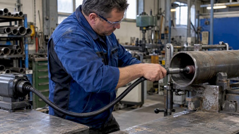
Deburring is a prime example. Cast and machined components often carry internal galleries, cross-bores, and recessed edges that are inaccessible to conventional spindles mounted on fixed axes. A flexible shaft fed through a guide tube routes a rotating deburring tool to the exact location of the burr without repositioning the workpiece or redesigning the fixture. This eliminates secondary handling operations and shortens cycle time. In automotive powertrain components, where complex castings carry dozens of intersecting passages, flexible-drive deburring stations reduce manual finishing labor substantially.
Grinding in confined spaces is another clear win. Bore grinding with a rigid spindle demands a straight line of sight from the motor to the bore entrance. When the bore is angled or offset from the machine column, fixturing becomes complex and tool reach is limited. A flexible shaft allows the grinding spindle to approach from any direction, conforming to the part geometry rather than forcing the part to conform to the machine. Flexible shaft machining advantages are especially visible in aerospace structural components and hydraulic manifolds with complex internal geometry.
Polishing of contoured surfaces requires consistent contact force and controlled surface speed. Flexible drives support this by transmitting smooth, uniform rotation to polishing heads on curved surfaces. In automotive exterior finishing and medical implant polishing, surface quality requirements are tight. The vibration-absorbing properties of the shaft prevent chatter marks and help maintain consistent contact between the polishing pad and the workpiece.
Common process problems that flexible drives resolve:
- Equipment jamming caused by angular misalignment between the spindle and the bore
- Excessive maintenance cycles on rigid drive trains exposed to grinding debris
- Inability to reach recessed features without manual touch-up operations
- Vibration transfer to the workpiece, causing dimensional variation in finish-ground bores
- Inflexible machine layouts that cannot adapt when part geometry changes between product variants
Flexible shaft systems support speeds from 46 to 9,320 rpm with motor ratings up to 5 HP (3.7 kW), covering the full performance range required for high-production automotive deburring and grinding.
These principles transfer directly to electronics manufacturing (precision routing of miniature grinding spindles), medical device production (internal finishing of implant cavities), and general automation where end-effector compactness is critical. To quantify impact on overall output, machinery efficiency improvement data provides useful benchmarks. For workflow integration guidance, a streamlined manufacturing workflow framework helps translate drive selection into process-level improvements.
Why flexibility is shaping the future of industrial drive design
Conventional wisdom in machine design has long treated flexible drives as a niche solution, appropriate only when a rigid shaft simply cannot fit. That view is increasingly outdated. The broader shift toward compact, modular, and reconfigurable machine cells means that alignment-sensitive rigid drive trains carry a hidden cost: they constrain machine architecture before design even begins.
As automation density increases and collaborative robots take positions inside legacy machine envelopes, the ability to route torque around obstacles without adding gearbox stages or complex linkages becomes a core design enabler. Ignoring vibration and alignment tolerance in the specification phase leads to structural resonance problems discovered only during commissioning, at significant cost.
The practical wisdom here is to evaluate total system performance rather than individual torque specifications in isolation. A flexible drive rated at 1 HP that eliminates two alignment brackets, one coupling, and a quarterly maintenance inspection delivers more system value than a rigid alternative with identical power throughput. For deeper insight into this approach, the advanced machining advantages resource covers specification strategies for demanding production environments.
Pro Tip: When designing for future adaptability, specify flexible drive systems with standardized end couplings. If the machine layout changes or the driven tool changes in a future product generation, the flexible shaft can often be retained and only the terminal coupling replaced. This significantly reduces retrofit cost and engineering time.
Explore flexible drive solutions for your engineering challenges
BIAX Flexwellen designs and manufactures industrial flexible shafts and drive systems for demanding production environments. Whether the requirement is a standard shaft for a deburring station, a custom-engineered configuration for a robotic end-effector, or a complete drive system for a precision finishing line, BIAX Flexwellen provides engineering guidance from initial specification through commissioning. The flexible shaft applications resource covers the full range of industrial use cases, while the engineering compact drive guide provides a structured framework for specifying the right drive for your geometry and performance requirements. Contact the engineering team directly for application support and custom configuration inquiries.
Frequently asked questions
What is the main advantage of flexible drive solutions over rigid shafts?
Flexible drive solutions handle misalignment up to 180 degrees and absorb vibration passively, enabling compact equipment designs that rigid shafts cannot accommodate without additional alignment hardware or complex linkages.
How much misalignment can a flexible drive shaft handle?
Most flexible shafts tolerate up to 180 degrees of misalignment while maintaining efficiency ratings above 90%, a capability that rigid couplings and universal joints cannot match without velocity fluctuations.
Are flexible drive solutions suitable for high-speed applications?
Yes. Flexible shaft systems support speeds up to 9,320 rpm with motor ratings up to 5 HP (3.7 kW), making them suitable for high-production grinding, drilling, and polishing across automotive and industrial sectors.
What applications benefit most from flexible drive solutions?
Deburring of complex castings, bore grinding of angled or offset features, surface polishing of contoured components, and any automation cell requiring compact or articulated torque transmission benefit most from flexible drive technology.
What are common mistakes when specifying flexible drive systems?
The most frequent errors are undersizing the shaft for peak torque, specifying a bend radius tighter than the shaft rating allows, and neglecting lubrication intervals, all of which accelerate wear and reduce service life significantly.
Recommended
- Flexible Shaft Drive Solutions: Unlocking Compact Efficiency
- Why flexible drives deliver reliable performance for engineers
- Benefits of flexible drive systems for manufacturing efficiency
- Flexible shaft guide: Engineering compact drive solutions
Related Topics
Send your spec inquiry
Custom flexible shafts for your application — we quote within 1 working day.