Torque, RPM, Bend Radius: Flex Shaft Tool Holder Specs for Aerospace
9 September 2026A flex-shaft tool holder, or werkzeugaufnahme, lets a stationary drive send torque through a flexible core to a lightweight, handheld tool for precision work in confined spaces. Choose it when access is restricted, when the operator needs pen-like control, or when repeatable shaft geometry matters more than raw power at the point of contact.
TL;DR:
- Shaft diameter and core construction must match the expected torque and RPM, with extra margin for peak transient loads to prevent premature failure.
- Maintaining proper bend radius is critical, as forcing shafts below their rated minimum radius accelerates wear, deformation, and reduces service life.
- Mounting methods that preserve the natural shaft curvature, such as overhead suspension or articulated arms, help prevent stress points and extend shaft longevity.
- Regular maintenance like cleaning and relubricating every 10 hours of operation can significantly reduce internal wear and overheating risks.
- Providing detailed load, environmental, and mounting specifications is essential for engineers to design reliable, custom flexible shafts suited to specific applications.
Table of Contents
- What Is a Werkzeugaufnahme Flexwelle and Where Is It Used?
- What Torque, RPM, and Bend Radius Limits Should You Design Around?
- Which Mounting Methods Keep the Shaft Geometry Stable?
- How Do You Install and Maintain a Flex Shaft for Maximum Life?
- What Do Engineers Need to Provide for a Custom Flexible Shaft Quote?
- What Should Engineers Take Away From Flex-Shaft Specification?
- How to Start a Flexible Shaft Specification Inquiry
- Sources
What Is a Werkzeugaufnahme Flexwelle and Where Is It Used?
The concept is a remote drive. A motor or spindle stays mounted at a fixed point, and torque travels down a flexible shaft core to a handpiece the operator holds directly. This separation is the entire value proposition: the mass and vibration of the drive unit stay off the tool tip, leaving a light, maneuverable instrument at the working end. Suspending the drive unit on a dedicated holder keeps the shaft in its natural curvature and reduces internal friction, which improves control at the tip.
That reduction in friction is not a minor detail. A shaft forced into a tight or irregular bend fights itself internally, and that resistance transfers back to the operator as reduced feel and inconsistent cutting or polishing pressure. A properly suspended shaft holds a smooth, repeatable arc, so the handpiece behaves the same way stroke after stroke.
This matters most in a specific set of applications:
- Deburring and edge-breaking on cast or machined parts where the tool must follow a contour, not just touch a flat surface.
- Polishing operations where consistent pressure and speed determine surface finish quality.
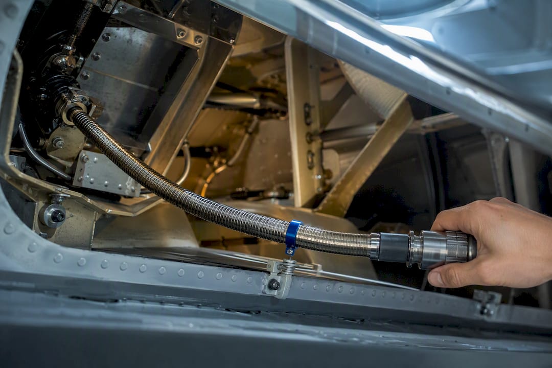
- Access into confined aerospace assemblies, including areas around flap and slat actuation linkages, thrust reverser mechanisms, and valve override housings, where a rigid drive simply will not fit.
- Fine finishing around complex geometry such as fillets, internal bores, and structural joints.
The tool holder itself is the interface component. It anchors the drive end, manages the shaft’s transition point, and in many configurations offers a mounting method that keeps the shaft’s bend radius consistent across repeated use. Get that interface wrong and every downstream benefit of the flexible shaft design erodes.
What Torque, RPM, and Bend Radius Limits Should You Design Around?
Four variables govern whether a flexible shaft survives its duty cycle or fails prematurely: torque, RPM, shaft diameter with core construction, and minimum bend radius. None of them can be specified in isolation.
Continuous torque capacity scales with shaft diameter and core wire construction. A shaft built for light polishing work will not tolerate the peak torque spikes common in aggressive deburring, even briefly. Shaft life correlates directly with the interaction of motor speed and bending severity: larger diameters and stiffer core windings extend service life under higher torque, but they also raise the minimum bend radius, which can conflict with a tight installation envelope.
RPM introduces a second constraint: heat. Every rotation inside a curved sheath generates internal friction, and friction becomes heat that has to dissipate through the sheath wall or degrade the internal lubricant. Running near the top of a shaft’s rated RPM in a tight bend accelerates bearing wear far faster than the same RPM in a gentler curve.
Bend radius undersizing is the most common specification error. Force a shaft below its rated minimum radius and you get accelerated core wear, increased friction, and in the worst case, permanent core deformation that shows up as vibration or torque loss within weeks.
- Match continuous torque to shaft diameter first, then verify peak torque headroom for transient loads.
- Treat RPM and bend severity as a paired constraint, not two separate specs.
- Confirm collet size, coupling geometry, and axial alignment tolerance before finalizing the interface.
- Never specify a working bend radius at or below the manufacturer’s stated minimum.
Pro Tip: When routing is tight and torque demand is moderate, it is usually better to step up one shaft diameter size than to force a smaller shaft below its rated bend radius. The added diameter costs you routing clearance, not service life.
Which Mounting Methods Keep the Shaft Geometry Stable?
The mounting method determines whether the shaft holds the curvature it was designed for or gets forced into stress points that shorten its working life. Four approaches cover most industrial and precision-finishing installations:
- Bench-hung holders. These offload the weight of the drive unit onto a fixed bracket, so the operator never carries anything heavier than the handpiece itself. They work best for stationary, repetitive tasks where the part comes to the operator.
- Adjustable-height stands. A telescopic column lets the operator set drive height once and keep it consistent across a shift, which matters for repeatable curvature when multiple people share one station.
- Articulated arms. These route the shaft around fixed obstacles, such as tooling fixtures or structural frame members, without introducing an unplanned tight bend partway along the shaft’s length.
- Suspended overhead mounts. Common where floor space is limited, these keep the shaft hanging in a natural downward curve rather than fighting gravity across an awkward horizontal run.
Workplace geometry drives the choice as much as the shaft’s own specification does. Bench thickness affects clamp reach, overhead clearance limits articulated arm swing, and operator reach distance determines whether a telescopic stand needs to extend further than its standard range. A flexible shaft designed for tight-space finishing still needs a mounting method that respects its bend radius, or the design work upstream is wasted at the point of installation.
How Do You Install and Maintain a Flex Shaft for Maximum Life?
Installation errors and deferred maintenance are the two most common causes of premature flexible shaft failure, and both are preventable with a short, disciplined routine.
Before first use, verify runout at the coupling, confirm every fastener on the coupling interface is torqued to spec, and trace the full routing path to eliminate any kink tighter than the shaft’s rated minimum bend radius. A kink introduced during installation behaves the same as an undersized bend radius: it accelerates wear from the very first cycle.
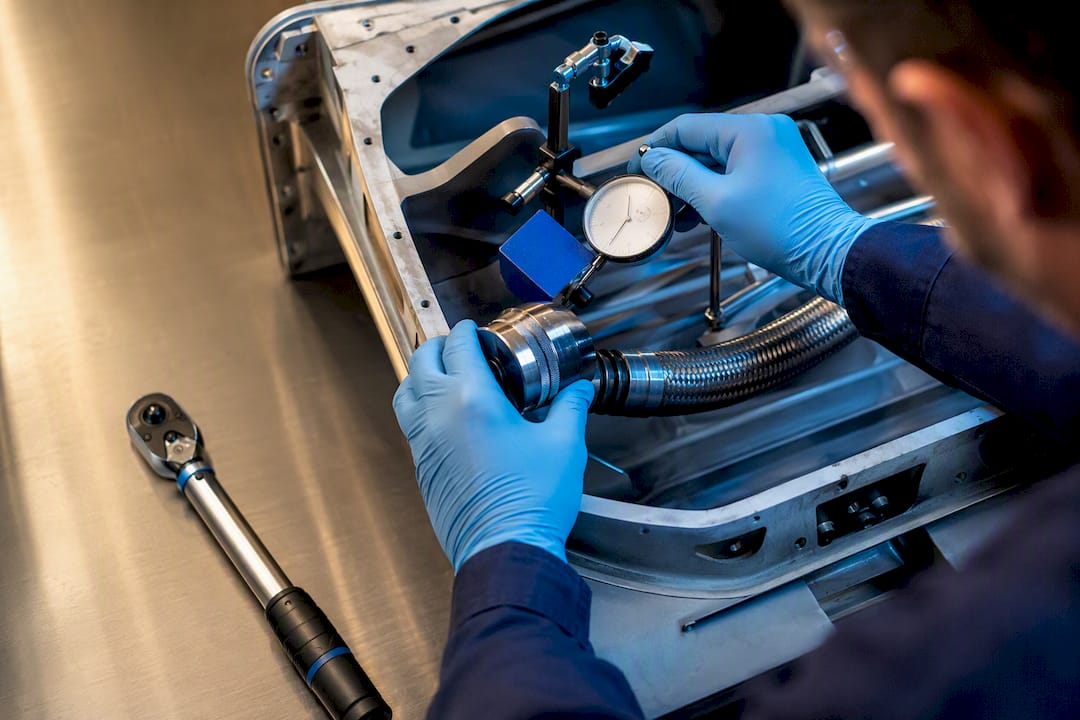
Once running, maintenance follows a simple rhythm. Cleaning the shaft core and applying a small amount of high-temperature bearing grease roughly every 10 hours of operation reduces internal wear and lowers overheating risk. That interval is a rule of thumb, not a fixed law. Heavier duty cycles or tighter bend radii call for shorter intervals.
Watch for three warning signs during operation:
- Unusual heat buildup at the sheath, particularly near a bend point.
- Vibration that was not present when the shaft was new.
- Noticeable torque loss at the tool tip under the same load that used to run smoothly.
Any of these signals calls for inspection before the next duty cycle, not after. For storage, coil the shaft to a radius equal to or greater than its minimum rating, and never leave it stored in a permanent tight bend, since that is how a shaft develops a set curve that no longer matches its original geometry.
What Do Engineers Need to Provide for a Custom Flexible Shaft Quote?
A supplier can only engineer a reliable match when the request includes measurable parameters, not general descriptions. Five categories of information turn a vague inquiry into an actionable specification.
- Load and speed data. Continuous torque and peak torque in Nm, continuous and peak RPM, and the duty cycle (intermittent versus continuous running).
- Environmental conditions. Expected bend radii along the full routing path, ambient and operating temperature range, and any contamination exposure such as coolant, dust, or chemical residue.
- Mechanical interfaces. Collet size, coupling drawings, required runout tolerance, and any axial play the application can tolerate.
- Integration details. Preferred holder type, mounting footprint, the full routing envelope, and the required overall shaft length.
- Acceptance criteria. Measured runout at delivery, a torque transmission validation method, and an expected lifetime estimate under the stated duty cycle.
Supplying torque transmission best practices data alongside your own drawings shortens the engineering review cycle considerably, since ambiguity in any one of these five categories usually forces a round of clarifying questions before a supplier can commit to a configuration.
What Should Engineers Take Away From Flex-Shaft Specification?
The core lesson is not about any single component. It is about respecting the relationship between torque, bend radius, and shaft geometry as one interconnected system rather than three separate line items on a spec sheet. Engineers who treat bend radius as a soft constraint, something to be worked around during installation, are the ones who see premature failures and unexplained torque loss six months into service.
Right-sizing the shaft diameter and core construction for the actual duty cycle, not the theoretical maximum, is the single highest-leverage decision in the entire process. Maintenance discipline, the routine of cleaning and relubricating on a consistent interval, is the second. Neither is complicated, but both require consistency rather than cleverness.
A manufacturer of industrial flexible shafts and drive solutions supports machine builders and industrial manufacturers with engineering guidance and custom configurations. For aerospace and precision-finishing engineers working through confined-space actuation or fine-finishing problems, that kind of upfront engineering support tends to matter more than any single spec sheet.
— Uli
How to Start a Flexible Shaft Specification Inquiry
Flexible shaft suppliers commonly offer both standard and custom-engineered flexible shafts, often backed by engineering support for torque, RPM, coupling, and routing requirements rather than only off-the-shelf catalog parts. That distinction matters most on aerospace-adjacent and confined-space applications, where a stock shaft’s bend radius or coupling interface rarely matches the installation without modification.
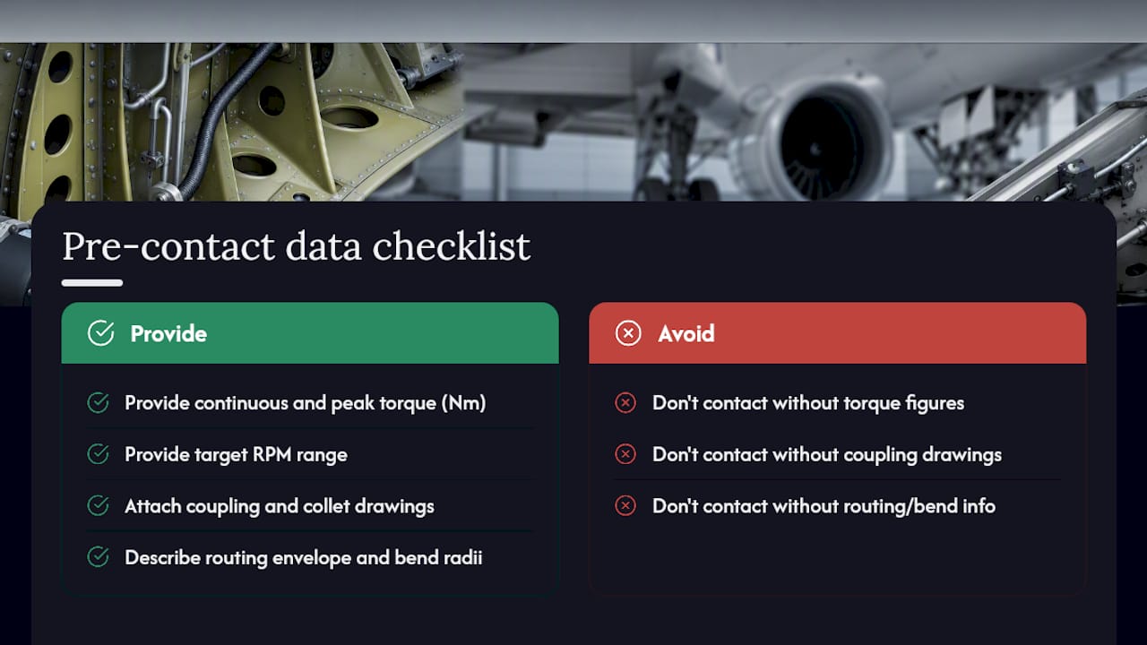
Before reaching out, gather your continuous and peak torque figures in Nm, your target RPM range, coupling and collet drawings, and the routing envelope including expected bend radii. Having those numbers ready lets the engineering team return a workable configuration on the first pass instead of a round of clarifying questions.
Engineers evaluating flexible shaft applications for industrial manufacturing can review typical configurations before submitting specifics, and design teams weighing shaft type entirely can start with the rigid versus flexible shaft selection guide. For teams sourcing broader aerospace machining and prototyping support alongside shaft integration, WJ Prototypes’ aerospace and UAV division covers adjacent manufacturing needs.
When your parameters are ready, submit them through the BIAX contact page to begin a technical review with the engineering team.
Sources
Recommended
- 3 Flexible Shaft Connection Dimensions Engineers Must Specify
- Custom Flexible Shaft Configuration Guide for Engineers
- How Torque Is Transmitted Through Flexible Shafts
- Torsion and Torque Explained for Design Engineers
Related Topics
Send your spec inquiry
Custom flexible shafts for your application — we quote within 1 working day.


