3 Flexible Shaft Connection Dimensions Engineers Must Specify
4 September 2026Three dimensions decide whether a flexible shaft fits: connection geometry (square, round, keyed, or flanged), shaft or pilot diameter with its key or flat size, and insertion or engagement depth to the shoulder. Alongside those, you need torque, rotational speed, and the installation’s minimum bend radius. Some interfaces follow published standards; most OEM hubs in tight installations still require dimensions matched by measurement rather than by catalog lookup.
TL;DR:
- Proper measurement of connection dimensions, including diameter, key size, and engagement length, is essential to ensure a correct fit during assembly.
- Standards like SAE J620 and DIN 6281 guide bolt circle and pilot diameters but require verification through measurement for legacy or custom hubs.
- Tight bend radii and high torque or RPM conditions significantly reduce the shaft’s rated capacity, necessitating derating during initial engineering calculations.
- Precise RFQ documentation, including CAD files and detailed dimensional tolerances, helps avoid costly redesigns and ensures first-time correct fitment.
- Material, surface finish, and operating conditions such as temperature and vibration directly influence the connection’s long-term stability and must be specified accurately.
Table of Contents
- Connector Types and the Dimensions Each One Needs
- How Do You Measure a Mating Hub Accurately?
- Which Standards Govern Flange and Coupling Dimensions?
- How Bend Radius and Torque Change the Usable Connection
- What Belongs in an RFQ for a Custom Connection?
- BIAX Engineering Guidance for Specification Packages
- Materials and Surface Finish at the Connection Interface
- Temperature, Vibration, and Connection Stability
- Author Perspective: Why Precise Connection Dimensions Save Time
- Get a Custom Flexible Shaft Quote from BIAX
- Primary Standards and Representative Datasheets
- Sources
Connector Types and the Dimensions Each One Needs
The connection interface on a flexible shaft falls into a handful of recurring geometries, and each one demands different callouts on a drawing or measurement sheet.
- Square drive (Vierkant): Record the width across flats and the engagement length. A common size in industrial flexible shafts is a small square insertion, though larger equipment uses proportionally larger squares.
- Round shaft with set screw: Capture the shaft outer diameter, the set screw thread size and location, and the flat length if one is machined for screw seating.
- Keyed connection: Note the shaft diameter, key width and depth, and keyway length, since a mismatch here causes rotational slip under load.
- Flanged coupling: Record the bolt circle diameter, pilot diameter, flange thickness, and the number and size of bolt holes.
- Crimped adapter: Document the adapter’s outer profile and the crimp length, since these are typically supplier-specific and not interchangeable across brands.
Drawing callouts differ by type: a square drive needs only width-across-flats and depth, while a flanged interface needs a pilot diameter plus a full bolt pattern. Getting the callout type wrong is one of the most common reasons for a delivered part not seating correctly.
How Do You Measure a Mating Hub Accurately?
A measurement error at this stage propagates directly into a fit failure at assembly, so working through the interface in a fixed order avoids missed dimensions.
- Measure the shaft outer diameter with calipers at two points along the engagement length to check for taper.
- Measure the bore or pilot diameter of the mating hub using a bore gauge, recording the minimum and maximum reading.
- Measure insertion depth or shoulder position with a depth micrometer, referencing a fixed face rather than the shaft tip.
- Record key or flat dimensions, including width, depth, and length, using calipers or a key gauge.
- Measure the bolt circle diameter for flanged interfaces, along with bolt hole size and count.
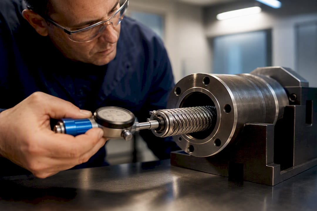
- Check runout by rotating the hub against a dial indicator to catch out-of-round conditions that calipers alone will miss.
Calipers, a depth micrometer, and a bore gauge cover most of this work. Note tolerances as a range, not a single number. A hub bore is rarely a nominal value in practice.
Pro Tip: Sketch the mating hub cross-section by hand, even roughly, and mark every dimension with its measured tolerance. Attach a photo with a ruler in frame, or a STEP file if the hub is already modeled. A rough sketch with real numbers beats a clean drawing with assumed ones.
Which Standards Govern Flange and Coupling Dimensions?
Flange-mounted coupling interfaces frequently reference SAE J620 or DIN 6281, which specify bolt circle diameter, pilot diameter, and flange thickness to keep motor and transmission housings compatible with a range of couplings. These standards work well when both the shaft supplier and the mating equipment manufacturer agree on which one governs the interface.
- Standard flanges: expect bolt circle, pilot diameter, and flange thickness to follow the referenced standard’s tables.
- Custom hubs: expect the manufacturer to request measured dimensions rather than a standard designation.
- Legacy or older equipment: standards compliance often can’t be assumed and needs field verification.
Many installations, particularly in industrial manufacturing applications with confined mounting envelopes, require bespoke matching to a specific drive housing even where a nominally applicable standard exists, according to guidance on flexible-welle connection standards. When a datasheet lists standards compliance, such as the flange dimensions noted in the ARCUSAFLEX product PDF, request the CAD model directly rather than re-deriving dimensions from a printed table. When it doesn’t, plan for a custom adapter from the start.
How Bend Radius and Torque Change the Usable Connection
Connection dimensions describe the interface, but they mean nothing if the shaft can’t deliver rated torque through the installed geometry. Torque capacity drops as bend radius tightens, which is one of the most overlooked causes of undersized shaft selection despite perfectly matched connection dimensions.
- Tighter bend radii reduce transmissible torque, sometimes substantially, compared with the shaft’s straight-line rating.
- RPM limits interact with bend severity: a shaft rated for a given speed in a straight run may need derating in a routed installation.
- Material and heat treatment choices affect how tightly a shaft can bend before permanent set or fatigue becomes a concern.
Machine Design’s coverage of flexible shaft installations confirms that tight bend radii measurably cut torque capacity in confined routing, and recommends derating against supplier tables rather than the nominal straight-shaft rating. For synchronization shafts or valve override systems where bend geometry is fixed by the airframe or housing, that derating step belongs in the initial torque transmission calculation, not as an afterthought once parts arrive.
What Belongs in an RFQ for a Custom Connection?
A specification package that arrives complete on the first submission avoids the clarification cycles that add days or weeks to a quote. The following fields cover what most engineering teams need to include.
- 2D drawing with critical dimensions and tolerances for every interface feature: diameter, depth, key or flat, bolt circle.
- STEP or other neutral CAD file, when available, to remove ambiguity that a 2D drawing alone can leave open.
- Torque and RPM requirements, stated as operating values, not just the motor’s nameplate rating.
- Installation bend geometry, including minimum bend radius and the number of bends in the routed path.
- Expected service life or cycle count, particularly for applications with repeated actuation such as flap and slat systems.
For precision or position-critical work, such as synchronization shafts in actuation systems, request tighter tolerance grades and specify runout and concentricity limits explicitly. General-purpose assemblies can typically work with looser bore and shoulder tolerances. Custom adapters generally carry longer lead times than stock connectors, so flag any expedited need at RFQ submission rather than after quoting begins.
BIAX Engineering Guidance for Specification Packages
Fielded installations reveal the same handful of specification errors repeatedly. Recognizing them before drawings go out saves a redesign cycle later.
- Assuming width-across-flats and a keyed seat are interchangeable, when they require entirely different tooling and mating geometry.
- Omitting insertion depth, leaving the axial position of the shoulder undefined.
- Overlooking runout or taper in the mating hub, which calipers alone won’t detect without a rotational check.
BIAX asks for a defined axial datum, typically the shoulder or flange face, plus a single axial dimension (referred to as Lx on many flange datasheets) to establish insertion depth without ambiguity, consistent with the approach outlined in the ARCUSAFLEX datasheet.
Pro Tip: Photograph the mating hub with a ruler placed against the bore and the hub’s orientation clearly visible. A single labeled photo resolves more ambiguity than a paragraph of written description.
Materials and Surface Finish at the Connection Interface
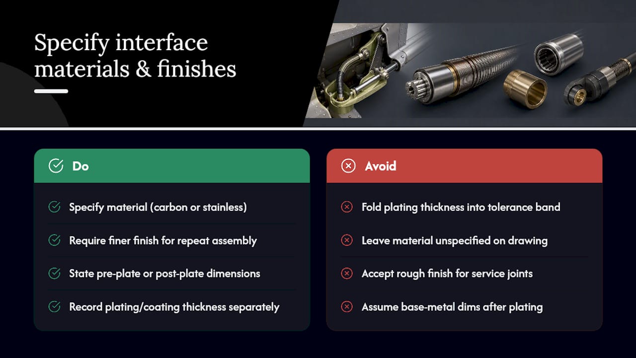
The connection interface’s material and finish affect fit as much as its dimensions do. Shaft cores and adapters are commonly manufactured from carbon or stainless steel, chosen based on the corrosion resistance and fatigue life the application demands. Stainless variants add cost but hold tolerance better under repeated thermal cycling, which matters where a connection sees frequent actuation rather than a fixed installed position.
Surface finish at the mating diameter directly affects fit repeatability. A rougher finish on a shaft’s insertion diameter increases effective clearance variation, since asperities compress differently on each assembly cycle. For interfaces that get assembled and disassembled repeatedly, such as service-access points on ground support equipment, a finer surface finish on both the shaft and hub reduces galling risk and keeps the measured bore diameter closer to nominal over the component’s service life.
Plating or coating adds a dimension that’s easy to miss on a drawing. A zinc or nickel plate thickness of even a few microns changes the effective diameter enough to bind against a bore machined to the base-metal dimension. When specifying a plated or coated connector, state whether recorded dimensions are pre-plate or post-plate, and note the plating thickness separately rather than folding it into the tolerance band. This single clarification prevents a disproportionate share of the “fits on the bench, binds on the machine” complaints that surface after delivery.
Temperature, Vibration, and Connection Stability
Operating conditions change a connection’s effective dimensions after installation, which is why a fit verified at room temperature on a bench doesn’t guarantee a fit in service.
Thermal expansion affects the shaft and hub differently when their materials differ. A steel shaft inserted into an aluminum housing, common in weight-sensitive aerospace applications, will see the bore expand faster than the shaft diameter as temperature rises, loosening a connection that measured tight at assembly. In the reverse temperature direction, that same pairing can tighten to the point of binding. Specifying the expected operating temperature range at RFQ stage lets the connection be matched with the right nominal clearance rather than a room-temperature fit.

Vibration acts on the connection differently than thermal cycling does. Sustained vibration, common in confined installation environments near engine or actuation hardware, tends to work fasteners loose and can cause micro-motion at a set-screw or keyed interface that gradually enlarges the mating bore through wear. A connection specified with a slightly tighter initial tolerance, or one using a positive-locking feature rather than friction alone, holds its dimensions longer under sustained vibration than a friction-only fit.
Neither effect shows up in a static measurement. Both belong in the RFQ’s operating-condition notes alongside torque, RPM, and bend geometry, not left to be discovered after the first vibration or thermal test cycle.
Author Perspective: Why Precise Connection Dimensions Save Time
Precise connection dimensions, submitted once and correctly, avoid the redesign cycle that costs far more time than the measurement itself. This matters most in synchronization and actuation systems, where a shoulder position off by a millimeter can mean a reworked bracket. Attach a sketch or STEP file when reaching out. It removes nearly all ambiguity from the first conversation.
— Uli
Get a Custom Flexible Shaft Quote from BIAX
Biax-flexwellen engineers custom flexible shaft connections for design teams who need a matched fit the first time, not after two rounds of clarification. Submit a 2D drawing with critical dimensions and tolerances, a STEP file if you have one, and a labeled photo of the mating hub. That package alone is usually enough to start a quote without a follow-up call. State torque, RPM, and installation bend geometry alongside the drawing so the derating calculation happens before parts are cut, not after a fit test fails.
Review typical connection details and application examples on the flexible shaft applications page, then send your specification package through the BIAX contact page to start a quote on a custom or standard configuration.
Primary Standards and Representative Datasheets
For flange geometry, consult SAE J620 or DIN 6281 directly for bolt circle and pilot diameter tables. For measurement practice on an unmarked or legacy hub, a representative manufacturer datasheet such as the ARCUSAFLEX PDF shows how axial datum and Lx dimensions are typically documented.
Sources
- SAE J620
- Flexible shafts eliminate obstacles (Machine Design)
- ARCUSAFLEX product PDF (representative datasheet)
Recommended
- Custom Flexible Shaft Configuration Guide for Engineers
- Custom flexible shaft design explained: engineer better solutions
- How to Select Flexible Shafts for Precision Machinery
- Engineering standards for flexible shafts: a practical guide
Related Topics
Send your spec inquiry
Custom flexible shafts for your application — we quote within 1 working day.


