Torque Transmission Best Practices for Flexible Shafts
24 July 2026Effective torque transmission in flexible shaft systems depends on four foundational decisions: material and coupling selection, correct service factor application, misalignment control, and a disciplined maintenance schedule. For aerospace and industrial engineers working with confined or high-speed installations, each of these decisions carries compounding consequences. A poorly sized gearbox, an uncompensated angular offset, or a missed re-torque check can cascade into bearing failures, efficiency losses, or structural fatigue. The practices below address all of these systematically.
Core best practices at a glance:
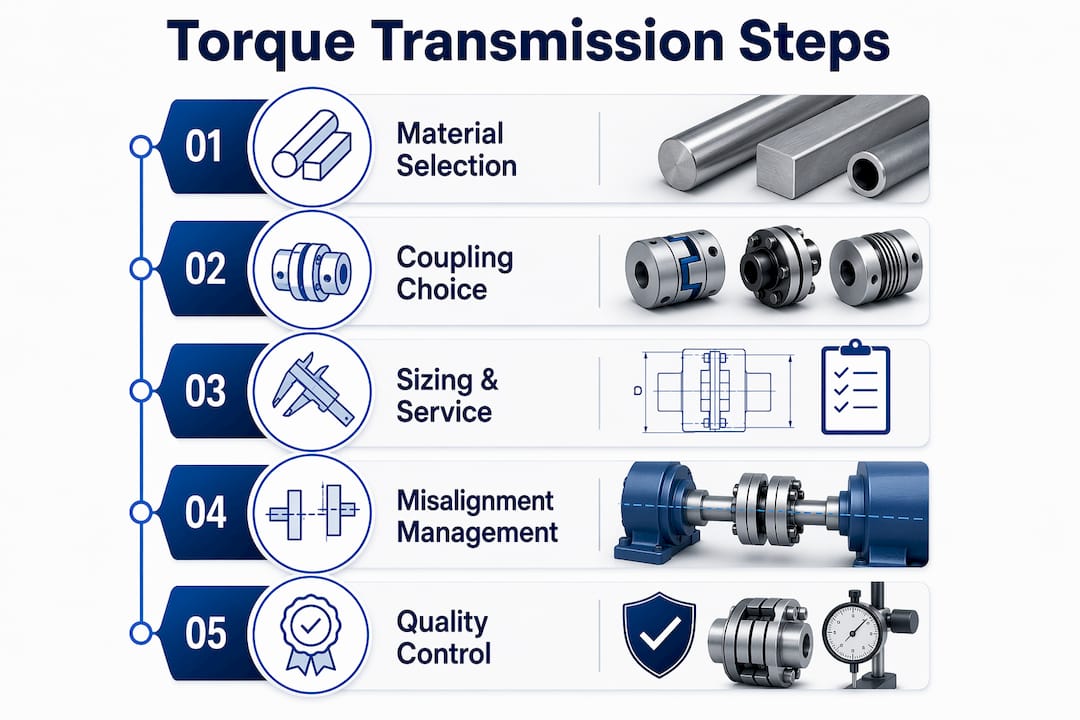
- Select materials based on load type: hardened steel for high-torque industrial drives, specialty alloys for corrosion and temperature resistance in aerospace
- Apply service factors to gearboxes, not motors: 1.0–1.25 for uniform loads, 1.75–2.5 for heavy shock
- Account for cumulative drivetrain efficiency losses when sizing prime movers
- Use bellows or diaphragm couplings where backlash-free precision is required; gear or sleeve couplings where misalignment compensation is the priority
- Perform alignment checks at commissioning and after any thermal cycle
- Recheck tightening torque after the initial commissioning period
- In aerospace applications, address axial thrust compensation and rotordynamic margins explicitly in the driveline design
- Apply AGMA or DIN standards for gear geometry and machining tolerances
Table of Contents
- 1. Fundamental principles of torque transmission in flexible shaft systems
- 2. How to select materials and couplings for demanding applications
- 3. Sizing considerations and service factors under operational loads
- 4. Managing misalignment and vibration in high-speed flexible shafts
- 5. Precision engineering practices for torque component quality
- 6. How Biax-flexwellen supports flexible shaft torque transmission design
- 7. Common failure modes and prevention in flexible shaft systems
- Key Takeaways
1. Fundamental principles of torque transmission in flexible shaft systems
Torque transmission is the transfer of rotational force through a mechanical driveline. In flexible shaft systems, this transfer occurs across components that may be offset, angled, or routed through confined spaces, which introduces constraints not present in rigid shaft designs.
Drivetrain efficiency is multiplicative, not additive. A typical industrial driveline with a motor at 93%, a VFD at 97%, a coupling at 99%, a gearbox at 95%, and a belt drive at 95% yields an overall efficiency often around 80.5%. That gap between input and output power must be recovered by oversizing the prime mover.
Thermal and mechanical stresses compound in high-speed flexible shafts. Rotational speed raises heat generation; higher loads increase friction. Both reduce transmitted torque and accelerate wear on tooth surfaces and bearing interfaces. Designing for peak transient loads, not just rated continuous loads, is the baseline requirement for reliable flexible shaft systems.
Pro Tip: Use the nondimensional scaling factor n√P (n in rpm, P in kW) to scale driveline components confidently across speed and power ranges. A design that works at one scale will perform identically at another if n√P is held constant.
2. How to select materials and couplings for demanding applications
Material selection determines wear resistance, fatigue strength, and thermal tolerance across the full service life of a torque transmission system.
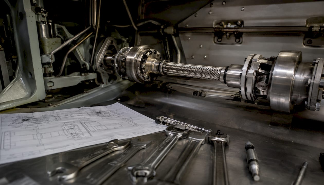
Hardened steel suits high-torque industrial drives: gears, splined shafts, and couplings benefit from its strength and durability. Specialty alloys are preferred for aerospace and marine environments where corrosion resistance, elevated temperature performance, and vibration damping matter more than raw strength. Surface treatments like nitriding diffuse nitrogen into steel surfaces, improving hardness and wear resistance without dimensional distortion.
| Coupling Type | Key Strength | Typical Application |
|---|---|---|
| Bellows | Backlash-free, high torsional stiffness | Servo drives, positioning systems |
| Diaphragm (titanium) | Low mass, high axial expansion tolerance | High-speed aerospace drivelines |
| Gear / Sleeve | Angular and parallel misalignment compensation | Industrial gearboxes, conveyors |
| Hydrodynamic | Non-contact torque transfer, torsional damping | Heavy load start-up, belt conveyors |
| Disc pack | Moderate misalignment, lower cost | General industrial applications |
Bellows couplings are the standard choice for backlash-free precision torque transmission in servo and positioning systems. Gear and sleeve couplings manage misalignment and reduce wear in industrial gearbox applications. For aerospace drivelines operating at high speed, titanium diaphragm couplings reduce mass overhang and improve rotordynamic margins. Hydrodynamic couplings transfer torque without mechanical contact, inherently damping torsional vibrations and limiting peak torque during heavy load start-up.
Sealing integrity and lubrication compatibility must be confirmed for each coupling type. Thermal expansion at operating temperature affects axial clearance; diaphragm couplings for aerospace applications are typically designed compressed in the cold condition and run stretched at operating temperature.
Pro Tip: For shaft coupling selection in confined aerospace installations, always specify the axial expansion range at operating temperature before finalizing coupling geometry. A coupling sized only for rated torque without thermal growth allowance will generate axial loads that degrade bearing life.
3. Sizing considerations and service factors under operational loads
Correct sizing prevents both fatigue failure from underdesign and wasted investment from unnecessary oversizing.
- Calculate output torque from actual load requirements using T = (HP × 5,252) / N.
- Identify the load classification: uniform, moderate shock, or heavy shock.
- Apply the appropriate service factor to the gearbox rating, not to the motor.
- Account for peak transient loads separately from rated continuous loads.
- Multiply required output torque by the service factor to determine minimum gearbox rating.
- Apply cumulative drivetrain efficiency to size the prime mover.
- Add safety margins for aerospace applications where failure consequences are severe.
| Load Type | Service Factor Range | Example Applications |
|---|---|---|
| Uniform | 1.0–1.25 | Fans, centrifugal pumps |
| Moderate shock | 1.25–1.75 | Conveyors, mixers |
| Heavy shock | 1.75–2.5 | Crushers, reciprocating compressors |
Applying service factors to the motor rather than the gearbox is a common design error. The gearbox must withstand shock loads directly; the motor only needs to deliver average continuous power. Misreading the load profile leads to undersized gearboxes and premature fatigue failures.
4. Managing misalignment and vibration in high-speed flexible shafts
Misalignment in flexible shaft systems originates from thermal expansion, manufacturing tolerances, vibration-induced wear, and installation errors. Angular and parallel offsets both generate cyclic bending loads that reduce component life and increase energy losses.
Common causes of misalignment:
- Thermal growth during operation
- Inadequate support rigidity
- Wear at bearing interfaces
- Installation errors at commissioning
Effects on system performance:
- Energy loss through cyclic bending
- Premature bearing and seal wear
- Elevated operating temperature
- Structural fatigue in shaft and coupling elements
Mitigation follows a clear sequence:
- Specify coupling type based on the expected misalignment envelope.
- Use pedestal-mounted transducers with lightweight diaphragm couplings to minimize mass overhang at high speeds.
- Conduct rotordynamic analysis to confirm critical speed margins before commissioning.
- Install vibration monitoring at bearing pedestals.
- Schedule alignment verification after the first thermal cycle and after any maintenance event.
Mass overhang from torque flanges degrades rotordynamic behavior and causes premature bearing failures. Lightweight titanium diaphragm couplings address this directly by reducing the overhung mass on gearbox and compressor shafts.
Pro Tip: For predictive maintenance of high-speed flexible shaft systems, install accelerometers at bearing pedestals and trend vibration signatures over time. A rising 1× or 2× component in the frequency spectrum typically indicates developing misalignment before any visible wear occurs.
5. Precision engineering practices for torque component quality
Gear micro-geometry refinement directly reduces stress concentrations and improves torque stability under fluctuating loads. CNC gear grinding and involute profile corrections such as tip relief and crowning minimize meshing impact, reduce noise, and extend component life.
Manufacturing sequence for precision torque components:
- Raw material selection and certification to AGMA or DIN standards
- Rough machining to near-net shape
- Heat treatment: quenching and tempering, or nitriding for surface hardness
- CNC gear grinding with involute profile correction
- In-process inspection using CMM, gear analyzers, and laser scanning
- Final surface finish verification
- Assembly with specified interference fits and tightening torques
| Quality Control Method | What It Detects |
|---|---|
| CMM (coordinate measuring machine) | Dimensional deviations, bore alignment |
| Gear analyzer | Profile error, pitch error, runout |
| Laser scanning | Surface finish, tooth geometry |
Nitriding improves surface hardness and wear resistance without the dimensional distortion associated with through-hardening. For flexible shaft components operating under cyclic torsional loads, a slight interference fit at hub-shaft connections reduces fretting fatigue by limiting micro-movements at the interface.
Pro Tip: Recheck tightening torque after the initial commissioning period. Fastener relaxation under initial load cycles is predictable and measurable; catching it at 50 hours prevents the loosening that causes misalignment and fretting damage over the full service interval.
6. How Biax-flexwellen supports flexible shaft torque transmission design
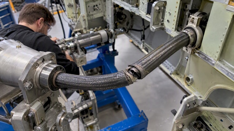
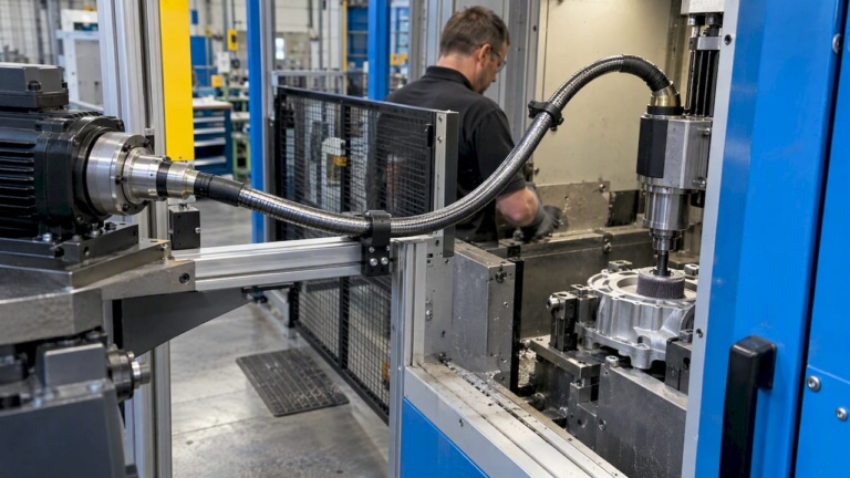
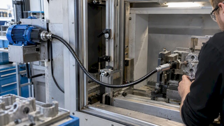
Biax-flexwellen (Schmid & Wezel GmbH) designs and manufactures flexible shafts and drive solutions for industrial and aerospace applications where torque must be transmitted through confined, angled, or hard-to-reach spaces. The product range covers standard components and custom configurations specified to torque, RPM, coupling interface, and protective sheath requirements.
For aerospace applications, Biax-flexwellen addresses the specific constraints of thrust reverser actuation, flap and slat drive systems, valve override mechanisms, and synchronization shafts in confined airframe structures. These installations require flexible shafts that maintain torsional stiffness under cyclic load while tolerating the angular offsets and axial movements inherent to aircraft structures.
Engineers working on custom projects can access technical guidance on flexible shaft applications covering torque capacity, bend radius limits, coupling interface geometry, and protective sheath selection. For non-standard requirements, Biax-flexwellen supports custom core and sheath configurations developed to the engineer’s specific load and installation envelope.
Contact resources for engineering consultation and custom project support are available through the Biax-flexwellen engineering contact page.
7. Common failure modes and prevention in flexible shaft systems
Flexible shaft failures follow recognizable patterns. Understanding the failure mode determines the correct prevention strategy.
Torsional fatigue is the most common failure in undersized or shock-loaded flexible shafts. It originates at stress concentrations: keyways, spline roots, and coupling interfaces. Prevention requires correct service factor application and surface treatments that improve fatigue resistance at these locations.
Fretting wear at coupling interfaces develops when micro-movement occurs between mating surfaces under cyclic load. A slight interference fit, confirmed tightening torques, and the 50-hour re-torque check address this directly.
Bearing failure from mass overhang is specific to high-speed applications where torque flanges or heavy couplings add overhung mass to shaft ends. Replacing heavy flanges with lightweight diaphragm couplings and using pedestal-mounted measurement systems eliminates this failure mode.
Lubrication breakdown accelerates wear on gear tooth surfaces and spline interfaces. For high-speed gearboxes, oil jet lubrication maintains film integrity and provides adequate cooling. Grease-lubricated systems require interval-based replenishment matched to operating temperature and speed. Contaminated lubricant increases churning losses and raises operating temperature, compounding wear.
Misalignment-induced fatigue develops gradually after installation. Thermal growth, support settlement, and bearing wear all shift shaft centerlines over time. Drivetrain efficiency monitoring combined with periodic alignment checks catches developing offsets before they reach failure thresholds.
Key Takeaways
Flexible shaft torque transmission reliability depends on correct service factor application, coupling selection matched to the misalignment envelope, and a disciplined post-commissioning inspection schedule.
| Point | Details |
|---|---|
| Apply service factors to gearboxes | Use appropriate service factors based on load type, such as lower factors for uniform loads and higher factors for heavy shock; never apply to the motor. |
| Account for cumulative efficiency | A typical driveline reaches ~80.5% overall efficiency; size the prime mover accordingly. |
| Control mass overhang at high speed | Lightweight titanium diaphragm couplings reduce overhung mass and protect rotordynamic margins. |
| Re-torque at 50 hours | Recheck all coupling and fastener tightening torques exactly 50 hours after commissioning. |
| Match coupling type to application | Bellows for backlash-free precision; diaphragm for aerospace; gear/sleeve for misalignment compensation. |
Recommended
- Optimizing Torque Transmission: A How-To Guide for Engineers
- Optimizing Torque Transmission Methods for Engineers
- Industrial Torque Transmission Explained for Engineers
- Flexible Shafts in Automation: Precision in Tight Spaces – BIAX Flexwellen
Related Topics
Send your spec inquiry
Custom flexible shafts for your application — we quote within 1 working day.