Rigid vs flexible shafts: Selection guide for industrial drives
3 May 2026TL;DR:
- Many engineers default to rigid shafts, viewing flexibility as a compromise rather than a deliberate design choice.
- Selecting between rigid and flexible shafts requires evaluating geometry, loading, environment, and lifecycle cost carefully.
Many engineers reach for rigid shafts by default, treating flexibility as a compromise rather than a deliberate design choice. This assumption costs real money in complex machine layouts where forced alignments, additional brackets, and extended maintenance windows add up. The reality is that selecting between rigid and flexible shaft solutions requires a structured evaluation of geometry, loading conditions, environment, and lifecycle cost. This guide covers the core differences, comparative performance attributes, real industrial application scenarios, and a practical decision checklist to support confident shaft selection in demanding manufacturing environments.
Table of Contents
- Understanding shaft types: Rigid vs flexible
- Comparing design and performance attributes
- Where each shaft type excels: Industrial application scenarios
- Key factors for selecting the right shaft
- Our perspective: Why the best shaft choice often defies tradition
- Discover engineered flexible shaft solutions
- Frequently asked questions
Key Takeaways
| Point | Details |
|---|---|
| Rigid vs flexible basics | Rigid shafts excel in aligned, high-torque setups while flexible shafts are ideal for complex layouts or tight spaces. |
| Performance factors | Selection hinges on torque demands, alignment, available space, and environmental conditions. |
| Reliability myths debunked | Flexible shafts now approach rigid shaft durability when engineered correctly for the use case. |
| Application-driven decisions | Use real-world operational needs as your primary selection criteria, not just tradition. |
Understanding shaft types: Rigid vs flexible
Rigid vs flexible shaft selection begins with a clear understanding of what each shaft type actually is and how each transmits mechanical power.
A rigid shaft is a solid, fixed mechanical element designed to transmit torque along a straight axis. It depends on precise alignment between the drive source and the driven component. Any angular or parallel misalignment introduces bearing loads and accelerated wear. Rigid shafts are manufactured from alloy steels or stainless steel, ground to tight dimensional tolerances, and require secure mounting in housings or bearing blocks to function correctly.
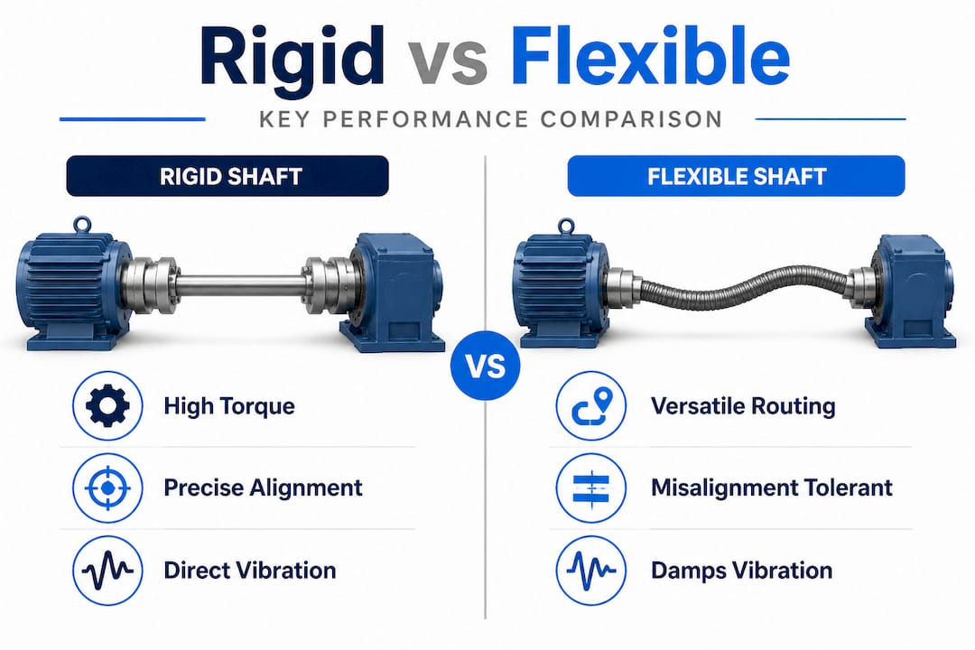
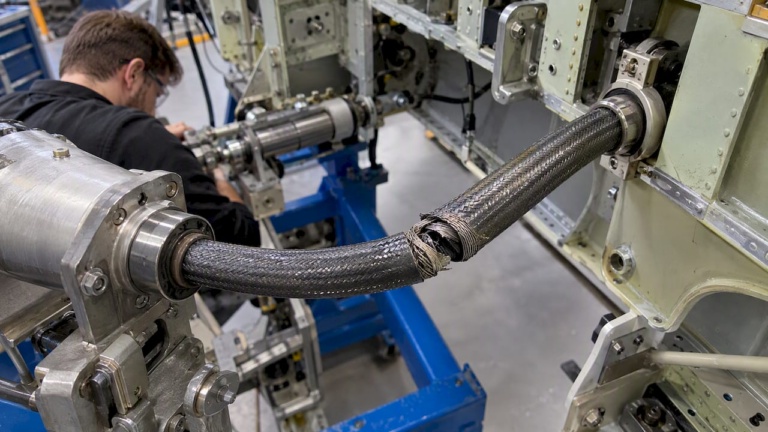
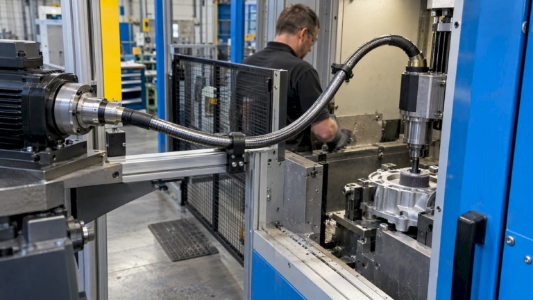
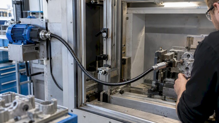
A flexible shaft transmits torque and rotation through a multi-layer wound wire core enclosed in a protective sheath. Because the core can bend, the shaft routes around obstructions, through curves, and into spaces a rigid shaft simply cannot reach. The construction uses multiple layers of high-tensile wire wound in alternating directions. This architecture transfers torque while accommodating bends, vibration, and angular deviation between drive and tool end.
Key characteristics of each type:
- Rigid shafts: Fixed geometry, precise alignment required, high torque capacity, suited to straight unobstructed layouts
- Flexible shafts: Adaptable routing, bend radius tolerance, torque transmitted through wound-wire core, well suited to complex machine geometries
- Core material: Rigid shafts use solid bar or hollow tube stock; flexible shaft cores use layered wire wound to specific pitch and diameter
- Protective elements: Flexible shafts use outer casing or sheaths to contain the core, provide lubrication retention, and protect against environmental contamination
As noted in technical practice, rigid shafts maintain alignment and transmit torque in straight, unobstructed layouts. That is their primary strength and their primary limitation. When layout geometry introduces bends or requires offset drive paths, the rigid shaft demands mechanical compensation through couplings, gearboxes, or intermediate supports, each of which adds cost, potential failure points, and installation complexity.
“The choice between rigid and flexible shafts is not a question of quality or reliability. It is a question of matching the right mechanical solution to the actual geometry and dynamic demands of the application.”
Flexible shaft technology does not inherently mean lower performance. Modern flexible shafts operate reliably at speeds exceeding 20,000 RPM in precision finishing applications and deliver consistent torque over extended service intervals when correctly specified and maintained.
Comparing design and performance attributes
With definitions in place, the next logical step is to see how the two shaft types measure up in practice, attribute by attribute.
Flexible shafts allow for versatile routing and can operate where rigid shafts are impractical. This single attribute changes the calculus across a wide range of machine designs and retrofit projects. The table below provides a structured side-by-side comparison of the most relevant engineering attributes.
| Attribute | Rigid shaft | Flexible shaft |
|---|---|---|
| Alignment requirement | Precise, fixed | Tolerant of angular and offset deviation |
| Installation complexity | High in complex layouts | Lower in constrained or curved paths |
| Torque capacity | High (limited by material cross-section) | Moderate (dependent on core diameter and bend radius) |
| Vibration handling | Transfers vibration to bearings | Absorbs and dampens vibration along the sheath |
| Maintenance needs | Bearing inspection, alignment checks | Lubrication, sheath inspection, bend radius compliance |
| Failure modes | Bearing failure, fatigue fracture under misalignment | Core fatigue at excessive bend, sheath wear |
| Design flexibility | Low | High |
| Environmental protection | Housing-dependent | Sheath provides inherent protection |
| Lifecycle cost in complex layouts | Higher | Lower |
The torque transmission capabilities of flexible shafts deserve specific attention. Engineers sometimes underestimate flexible shaft torque ratings because they associate wound-wire construction with weakness. In practice, the flexible shaft technology benefits include consistent torque delivery across a wide range of bend radii when the shaft is properly sized for the application. Exceeding the rated minimum bend radius is the primary cause of premature core fatigue, not the construction type itself.
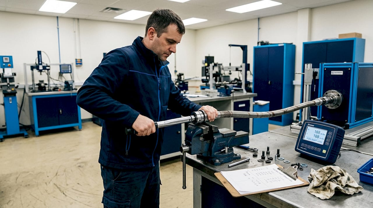
Vibration behavior also differs significantly. A rigid shaft transmits torsional and radial vibration directly to connected bearings and housings. In high-frequency finishing processes such as deburring or grinding, this vibration transmission affects tool performance and operator ergonomics. A flexible shaft’s wound-wire construction and sheath combination absorbs a portion of this vibration before it reaches the tool end or the operator.
Pro Tip: Always match shaft flexibility to the application’s geometry and dynamic loading profile. Over-bending a flexible shaft to save space reduces its rated torque capacity and accelerates core wear. Specify minimum bend radius as a binding design constraint from the start.
Installation clearance is another practical differentiator. Rigid shafts need straight, accessible runs with space for bearing housings and alignment tools. Flexible shafts only need clearance for the sheath diameter. This difference becomes significant in retrofits, where machine access is already limited and adding bearing supports or couplings is not feasible.
Where each shaft type excels: Industrial application scenarios
Armed with a comparative perspective, let’s drill down into specific industrial applications to see how these differences play out.
Flexible shafts are often preferred in tight spaces or when alignment is difficult to maintain. The table below maps common industrial scenarios to the preferred shaft type and explains the reasoning.
| Application scenario | Preferred shaft type | Primary reason |
|---|---|---|
| High-speed grinding and polishing | Flexible | Vibration absorption, routing flexibility, ergonomics |
| Long straight conveyor drives | Rigid | High torque over distance, stable alignment |
| Deburring in confined machine housings | Flexible | Bend routing, compact installation footprint |
| Precision gear cutting machines | Rigid | Positional accuracy, zero compliance under load |
| Maintenance tools and inspection equipment | Flexible | Operator control, adaptable reach |
| Retrofitting existing machine layouts | Flexible | No realignment required, reduced disassembly |
| High-torque press or forming drives | Rigid | Maximum torque transmission, structural stability |
| Remote actuation in automated assembly | Flexible | Routing through complex machine geometry |
The following sequence illustrates how shaft type selection shifts with application demands:
-
High RPM long-distance transmission. Rigid shafts are well suited for direct-drive spindles and conveyor systems where power must travel along a stable, straight path at high rotational speeds. Flexible shafts lose efficiency at extreme lengths due to internal friction within the sheath, so rigid solutions dominate in these configurations.
-
Misaligned machine layouts. When drive and driven components cannot be brought into precise alignment due to space, structural constraints, or existing machine architecture, flexible shafts provide a direct solution without the need for intermediate couplings or gearboxes. This is particularly relevant when choosing the right shaft type for retrofitting older industrial equipment.
-
Tight installation spaces and testing equipment. Instrumentation, inspection tools, and test rigs often require torque and rotation delivery to points that are physically inaccessible with rigid shafts. Flexible shafts route through panels, around corners, and into confined assemblies without modification to the surrounding structure.
The design efficiency gains with flexible shafts are measurable in reduced component count, shorter installation time, and lower total system weight in many machine designs. Eliminating intermediate bearings, couplings, and alignment supports removes potential failure points and simplifies assembly.
For precision finishing and machining, flexible shaft solutions support consistent material removal rates by maintaining steady torque delivery at the tool end regardless of the operator’s hand position or working angle. This is a direct advantage in manual deburring, surface preparation, and polishing where the operator’s motion varies continuously.
Pro Tip: For retrofits, flexible shafts can simplify upgrades where space is tight or machine disassembly is impractical. Calculate the cost of bearing additions and alignment labor against the cost of a properly specified flexible shaft assembly. In most constrained retrofit scenarios, the flexible shaft solution is faster, cheaper, and more reliable over the service life.
Key factors for selecting the right shaft
With practical applications mapped out, the next step is making a confident selection using all relevant factors.
Alignment, required torque, installation environment, and long-term maintenance should drive the shaft selection decision. These four factors form the core of a structured evaluation. Below is a practical selection checklist organized for design engineers and process engineers working through specification:
-
Define the loading profile. Identify peak torque, continuous torque, and cyclic loading patterns. Flexible shaft cores are rated for continuous torque under defined bend conditions. Exceeding these ratings under cyclic loading causes fatigue failure.
-
Establish required accuracy. Applications demanding tight angular position control or minimal torsional wind-up, such as precision machining or servo-actuated positioning, generally favor rigid shafts. Where tool-end compliance is acceptable or beneficial, flexible shafts are viable.
-
Assess the installation environment. Temperature extremes affect sheath material performance. Moisture, coolant, and abrasive debris require appropriate sheath and core material selection. Standard flexible shaft sheaths provide inherent protection against contamination that an open rigid shaft arrangement does not.
-
Map layout and geometric constraints. Measure minimum bend radius requirements and confirm the shaft routing path. Lock in the minimum bend radius as a non-negotiable specification before selecting core diameter and sheath type.
-
Plan for maintenance access. Rigid shaft systems require periodic bearing inspection and alignment verification. Flexible shaft systems require lubrication checks and sheath condition monitoring. Review maintenance tips for flexible shafts to build a realistic service plan into the design phase.
Common pitfalls in shaft selection include:
- Overlooking misalignment. Even small angular errors in rigid shaft installations cause disproportionate bearing loads and premature failure. Engineers who assume “close enough” alignment is acceptable will encounter reliability problems.
- Underestimating vibration impact. Cyclic and torsional vibration at high RPM can cause fatigue failure in rigid shaft systems without adequate dampening. In flexible shaft systems, operating beyond the rated minimum bend radius amplifies internal stress and accelerates core fatigue.
- Ignoring total lifecycle cost. Initial component cost is rarely the dominant factor. Installation labor, bearing replacement intervals, alignment tool costs, and downtime during maintenance should all be included in the total cost of ownership evaluation.
Quick reference summary:
- Choose rigid shafts for straight, high-torque, precision-critical applications with stable alignment
- Choose flexible shafts for complex routing, retrofit installations, vibration-sensitive processes, and constrained spaces
- Always specify minimum bend radius as a design constraint for flexible shaft selection
- Engage maintenance and shaft longevity planning early in the design process
Pro Tip: Involve maintenance and operations teams early in the shaft selection process. They carry practical knowledge about how equipment is accessed during service, what contaminants are present, and where previous drive components have failed. Their input often reveals constraints that design drawings do not capture.
Our perspective: Why the best shaft choice often defies tradition
Having reviewed all technical factors, it is worth pausing to consider why many organizations still default to rigid shafts and what a modern perspective looks like.
Industry tradition favors rigid shafts because they have been the standard for most of industrial history. Engineers learned on rigid shaft systems, specifications were written around them, and procurement processes reflect their dominance. Flexible shaft technology was viewed for decades as a specialized niche solution, useful only when rigid shafts were physically impossible to install. This perception is outdated.
Modern flexible shaft designs offer reliability and lifespan approaching those of traditional rigid shafts in suitable applications. In some layouts involving vibration, contamination, or access constraints, flexible shafts actually outlast rigid solutions because they are not subjected to the bearing loading and misalignment stresses that degrade rigid systems over time. This shaft lifespan insight should be part of every engineering team’s baseline knowledge when specifying drive components.
The more productive question is not “rigid or flexible by default?” but rather “which solution matches the specific constraints of this application?” This requires cross-disciplinary input. Mechanical designers, process engineers, maintenance teams, and procurement need to evaluate shaft selection together, not in isolation. When a design engineer specifies a rigid shaft without consulting the maintenance team, the result is often a system that performs acceptably at commissioning but deteriorates faster than expected in service.
Flexible shaft technology has matured significantly. Modern cores, precision-wound sheaths, and engineered coupling interfaces now support demanding applications in automated manufacturing, medical device production, and aerospace finishing processes. Treating flexible shafts as a compromise rather than a primary design option means missing real opportunities to simplify machine architecture and reduce total system cost.
Discover engineered flexible shaft solutions
If you are evaluating shaft selection for a current or upcoming machine design, BIAX Flexwellen provides the engineering depth and product range to support confident decisions. The engineering compact drive solutions guide covers shaft specification for space-constrained layouts in detail. For a broader view of where flexible shaft technology performs best, the industrial flexible shaft applications resource covers key sectors and process types. For application-specific guidance on torque ratings, coupling interfaces, and custom core configurations for your manufacturing environment, consult the BIAX Flexwellen team directly. Experienced application engineers are available to review your layout requirements and recommend the right solution.
Frequently asked questions
What are the most important criteria for choosing between rigid and flexible shafts?
Alignment, torque, installation environment, and maintenance should drive shaft selection decisions. Available installation space and geometric routing constraints are equally critical inputs in the evaluation.
Are flexible shafts less durable than rigid shafts?
Not necessarily. Modern flexible shaft designs offer durability close to rigid shafts when operated within proper application limits, including minimum bend radius and rated torque conditions.
Can flexible shafts transmit the same amount of torque as rigid shafts?
Flexible shafts transmit substantial torque but peak torque capacity is generally lower than comparable rigid shafts due to wound-wire construction and bend radius effects on core loading.
When should rigid shafts be avoided?
Avoid rigid shafts when alignment cannot be guaranteed or when layout geometry requires bends, offsets, or routing through confined spaces where straight shaft runs are not feasible.
What maintenance considerations are unique to flexible shafts?
Regular lubrication and inspection of bending stress points are critical for flexible shaft longevity, as outlined in expert maintenance practices. Sheath condition monitoring and bend radius compliance checks should be included in every scheduled service interval.
Recommended
- Flexible shaft applications for industrial manufacturing
- Shaft flexibility: the key to optimized industrial drives
- Flexible Shaft Drive Solutions: Unlocking Compact Efficiency
- How to Select Flexible Shafts for Precision Machinery
- Industrial Equipment and Components Manufacturer in China
Related Topics
Send your spec inquiry
Custom flexible shafts for your application — we quote within 1 working day.