Process Reliability in Deburring with Flexible Shafts
21 October 2026Process reliability in deburring with a flexible shaft depends on four things: a drive train that delivers stable speed and torque at the tool, a tool that follows part geometry without a rigid path, defined inspection of the result, and a drawing specification that states what “burr-free” means. This article covers each of these from the design engineer’s point of view, with attention to confined installation spaces such as those found in aerospace assemblies.
TL;DR
- A flexible shaft decouples the motor from the tool. This gives access to bores, pockets and cross-holes and allows compliance to absorb part and fixture variation.
- Process reliability comes from a controlled operating window: speed, torque, bend radius, contact force and tool wear limits, each defined and monitored.
- Visual checks alone do not verify internal cross-holes. Magnified inspection, tactile checks and lot-based documentation are the established practice.
- Drawing requirements must be explicit: edge condition per DIN ISO 13715 and surface texture per the ISO 21920 series.
- Early definition of torque, RPM, bend radius and coupling interfaces avoids redesign in the shaft assembly.
Table of Contents
- Why deburring is a process reliability problem
- Functional principle of a flexible shaft drive
- Compliance: why the drive train affects repeatability
- Defining the operating window
- Aerospace installation conditions
- Cross-holes, bores and hidden burrs
- Inspection and documentation
- Specifying the result on the drawing
- Our perspective
- Support for design and specification
- FAQ
- Contact
- Sources
Why deburring is a process reliability problem
Burrs form during cutting, punching, forming and machining. Their size and position vary with tool wear, material batch and cutting parameters. A deburring step that follows must therefore handle input variation and still produce an edge that meets a defined condition. In sectors such as automotive, aerospace and medical technology, burr-free components are often a stated requirement, and edge conditions are specified on drawings according to DIN ISO 13715.
In practice, failures of reliability rarely come from the abrasive alone. They come from one of the following:
- Tool selection that does not match the burr or the material. Tools that are too coarse or unsuitable damage the surface or leave burrs incompletely removed, as NCFertigung describes in its list of typical errors.
- Drive instability: speed drop under load, vibration, or heating of the shaft.
- Rigid tool paths on parts that are not perfectly located.
- Inspection that does not reach the feature that matters, for example an intersecting bore.
- Unclear acceptance criteria between design, production and quality.
A flexible shaft influences the first four directly. The fifth is a matter of specification and is treated further below.
Functional principle of a flexible shaft drive
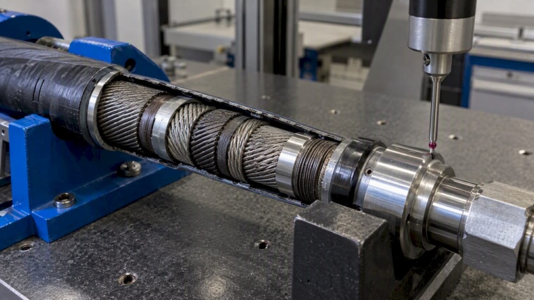
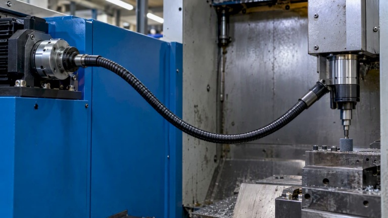
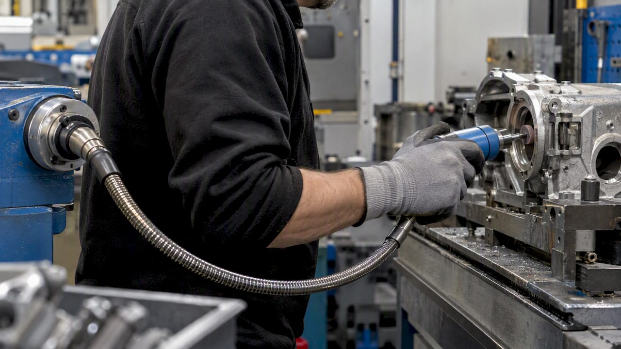
A flexible shaft transmits rotation and torque through a wound core running inside a protective sheath. The motor stays where installation space and cooling allow. The tool end, with a handpiece, spindle or tool holder, goes where the work is. This arrangement is used for deburring, grinding, polishing and cleaning, and in actuation tasks where a rigid shaft cannot follow the installation route.
For a design engineer, the relevant parameters are:
- Transmitted torque and speed. The core construction and diameter set the permissible torque and speed range. Higher speed at a given power means lower torque, which is the usual operating case in deburring.
- Bend radius. A smaller radius increases internal friction, heating and wear. The installation route should keep bends as large and as few as possible.
- Direction of rotation. Cores are generally wound for a preferred direction. The loading direction affects torsional stiffness and life, so it must be defined with the drive.
- Sheath and end fittings. The sheath protects the core and holds lubrication. The fittings define the interface to the motor and to the tool.
- Length. Torsional wind-up and losses increase with length. The shortest practical length is preferred.
BIAX publishes further background in its articles on flexible shaft design for tight-space finishing and industrial drive system basics.
Compliance: why the drive train affects repeatability
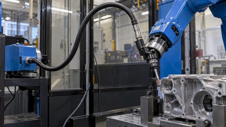
An automated deburring cell gives consistent motion, but it does not adapt to the part. ATI’s guidance on robotic deburring states that robots provide consistency but lack adaptability, and that compliant tooling is needed to accommodate part irregularities and fixture drift. The tool is effectively decoupled from the rigid robot path so that contact force stays uniform.
Two mechanisms are commonly used to create that compliance:
- A compliant tool head, for example a radially compliant air-turbine unit.
- A flexible drive between a fixed motor and a lightweight tool head, where the shaft itself allows the tool to move relative to the motor.
The second mechanism has a further effect. The moving mass at the tool is small, because the motor does not travel with it. This reduces inertia at the end of a manipulator and makes it easier to hold a defined contact force. It also keeps heat and vibration from the motor away from the point of work.
For series use, the points that determine reliability are:
- Constant contact force. Define the force window and verify it, either through a compliant stage or a monitored feed.
- Defined tool path tolerance. Compliance covers deviation, not unlimited error. Determine the range that the compliance has to absorb.
- Fixed shaft routing. In a moving cell, the shaft path changes with the pose. Check the minimum bend radius over the full range of motion, not only in the home position.
- Wear compensation. Abrasive tools lose size and cutting capability. Define replacement intervals, or measure and compensate.
A detailed treatment of the numerical inputs for a cell is available in 3 exact figures vendors need for deburring cell flex shafts.
Defining the operating window
A stable process has a documented operating window. For a flexible shaft deburring drive, the following values are needed before a shaft is selected.
| Parameter | Why it matters | Typical consequence if undefined |
|---|---|---|
| Required tool speed (rpm) | Sets cutting speed at the abrasive or cutter and the shaft loading | Burr removal incomplete or surface damage |
| Torque at the tool | Determines core size and the motor’s torque reserve | Speed drop under load, overheating |
| Direction of rotation | Matches the core winding to the load | Shortened service life |
| Minimum bend radius in operation | Limits friction and heating | Premature wear, speed fluctuation |
| Shaft length | Affects wind-up and losses | Inconsistent speed at the tool |
| Duty cycle | Defines thermal load and lubrication interval | Heat build-up, failure of the sheath |
| Coupling interfaces | Defines the fit to motor and tool | Misalignment, runout, vibration |
| Ambient conditions | Temperature, contamination, coolant exposure | Lubricant loss, corrosion |
Speed deserves attention. Small abrasive and cutting tools used on holes and edges often need high speeds, while the shaft itself must be run within its rated limits. BIAX lists drive and tool shafts in its Antriebs- und Werkzeugwellen range, which is designated for speeds up to 50,000 rpm. The permissible value for a specific shaft depends on its diameter, length and routing, so it is confirmed against the application data.
Aerospace installation conditions
Aerospace assemblies combine tight packaging, high accuracy requirements and strict documentation. Flexible shafts appear in several functions in these systems, and the same design constraints that govern a deburring drive apply to them: defined torque, limited bend radius, controlled backlash and a clean interface.
Typical installation cases include:
- Flap and slat actuation. Rotation is transmitted from a central drive over distance to positions along a wing. Where a rigid line cannot follow the structure, a flexible element can bridge offsets.
- Thrust reverser systems. Actuation and synchronization functions take place in confined nacelle spaces with temperature variation and vibration.
- Valve override systems. A manual or remote override reaches valves that are not directly accessible.
- Synchronization shafts. Two or more actuators must move in step. Torsional stiffness and low backlash of the connecting shaft determine the synchronization error.
The deburring of components in these systems is a separate topic from the shafts inside them, but both have the same underlying requirement. The part geometry is complex and access is limited, so the tool must reach features that a rigid spindle cannot. Aerospace parts include intersecting bores, pockets and thin-walled sections where a burr can detach during service and a missed burr is a quality escape, not only a cosmetic defect.
BIAX covers the finishing side in its guides on edge finishing for aerospace engineers and industrial polishing step by step for aerospace engineers. Actuation shafts are described under Betätigungswellen.
Cross-holes, bores and hidden burrs
Cross-holes are a recurring difficulty. A production-machining article quoted in an Orbitool document calls cross-holes an Achilles’ heel of subtractive manufacturing, because burrs form where bores intersect and are hard to reach. The same holds for a flexible-shaft-driven tool: it can reach the intersection, but a defined tool type, speed and feed are needed for the result to be repeatable.
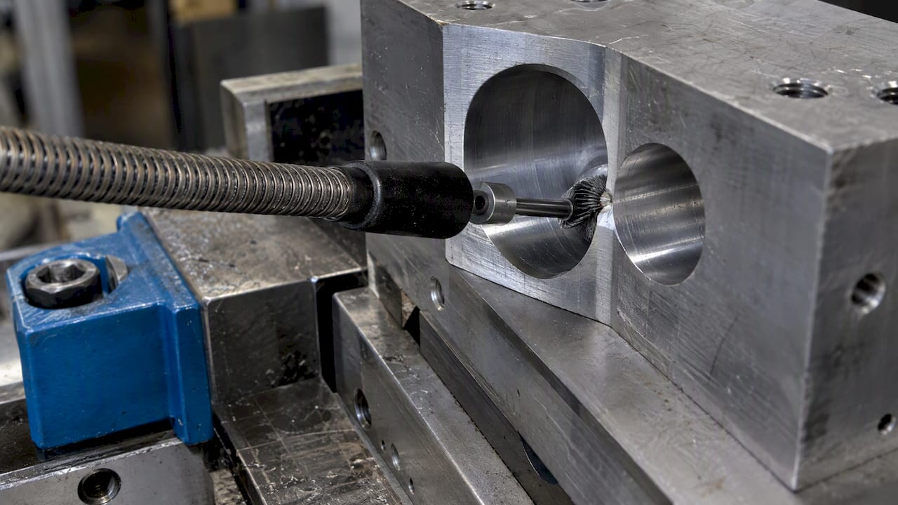
Flexible abrasive tools are a common choice for this task. A study on flexible abrasive tools for hole deburring in superalloys describes tools in which small abrasive balls on a nylon filament act independently, which supports centering and self-alignment in the hole. Such tools are driven by a spindle or a flexible shaft, and the drive must hold speed stable so that the abrasive acts the same way on every part.
Points to define for hole and cross-hole deburring:
- Tool diameter relative to the smallest bore, with clearance.
- Speed range and direction, to avoid tool whip or premature wear.
- Immersion depth and dwell time, ideally set by a stop or program, not by the operator.
- Material removal limit, so that the bore edge geometry stays within the tolerance in the drawing.
- Cleaning after deburring, since removed particles remain in the bore.
Inspection and documentation
A deburring process is reliable only if its result is verified. The NCFertigung guide recommends that for aerospace and high-performance components deburring should be validated by systematic inspection, including magnified visual checks of about 40x and tactile measurement. It also notes that visual inspection alone does not suffice for internal cross-holes, and that sample testing and photo documentation for each production lot support repeatability.
A workable inspection plan has these elements:
- Defined acceptance criteria per feature: for example a maximum burr height or an edge radius range, referenced to the drawing.
- Method per feature. Borescope or magnification for internal edges, tactile gauges or a fingernail-free tactile test where the drawing allows, and microscope measurement for the critical edges.
- Sampling per lot, with photographs linked to lot and part number.
- Reaction plan. Which parameter is checked first when a nonconforming part is found: tool wear, speed, contact force or fixturing.
- Process data. Where possible, log motor current or speed, since a change in load shows tool wear or a shaft problem before the part fails inspection.
The same principle applies in other edge-processing steps. A paper on edge quality after laser cutting (in Polish) covers sample inspection and photo documentation per production lot in a neighboring process, and it is a useful reference for how to structure the records.
Process sequence also matters. A fixed order of deburring, grinding, fine grinding, polishing and cleaning prevents later steps from reintroducing defects or contamination, and each step should have its own acceptance criteria.
Specifying the result on the drawing
Unclear drawing requirements are a cause of dispute and rework. Two standards govern most of what a deburring specification must say.
Edge condition. DIN ISO 13715 defines how edges with undefined shape are indicated on drawings, including burr and undercut limits. Overviews of deburring standards also list DIN 8593 for classifying deburring processes. A specification of “burr-free” without a numerical edge condition leaves too much to interpretation.
Surface texture. The ISO 21920 series has replaced ISO 1302, ISO 4287, ISO 4288 and ISO 13565. According to the DGQ summary, ISO 21920-1 covers indication on drawings, ISO 21920-2 terms and parameters, and ISO 21920-3 specification operators. Parameters are now defined directly rather than through earlier pre-measurement heuristics. If a drawing refers to roughness after deburring, grinding or polishing, the symbol and parameters should follow the new series, and the measurement setup must be consistent with it. The PTB report on the new series explains the changes for stylus measurement. Differences in how the primary profile is obtained are also explained by Digital Surf.
A practical consequence: roughness values from older drawings and new drawings should not be compared directly without checking which standard and which filter settings apply.
Our perspective
In our experience with flexible shaft drives, process problems in deburring are traced back to the drive far less often than to missing inputs. A shaft can be selected correctly only when torque at the tool, speed, direction of rotation, length, routing and coupling are known. When one of these is estimated, the result is a shaft that runs at the edge of its limits, and the deburring result varies with temperature and tool wear.
We therefore recommend working in this order:
- Define the burr and the required edge condition on the drawing.
- Select the tool and determine its speed and torque demand under real contact.
- Determine the routing and the smallest bend radius over the whole motion range.
- Specify the shaft, the sheath and the end fittings for this load case.
- Run a trial with inspection per the plan above, and adjust before series release.
Prototypes and small batches are useful at step 5, because they show actual shaft behavior before the design is frozen. For aerospace work, the same sequence applies, with the documentation requirements of the program added.
— Uli
Support for design and specification
BIAX Flexwellen manufactures standard and custom flexible shafts. The range includes flexible shaft cores by the meter, Antriebs- und Werkzeugwellen, Betätigungswellen and Sonderlösungen und Prototypen for configurations that depend on torque, speed, coupling interfaces and shaft design. Application examples are collected on the product examples page.
FAQ
Which shaft data should be defined before a deburring drive is specified?
Torque at the tool, operating speed, direction of rotation, shaft length, minimum bend radius over the full motion range, duty cycle and coupling interfaces. Ambient conditions such as temperature and coolant exposure should be added. Without these values, the shaft cannot be assessed for service life.
Can a flexible shaft make a robotic deburring process more stable?
It can contribute. A flexible drive reduces the mass at the tool and allows the tool to follow part and fixture deviations, which supports uniform contact force. ATI’s guidance on robotic deburring names compliance as the way to handle fixture drift and part irregularities. The shaft routing must still stay within its bend radius limits throughout the robot’s motion.
How is deburring of internal cross-holes verified?
Visual inspection from the outside is not sufficient. Magnified inspection with a borescope or similar equipment, tactile checks and lot-based sampling with photographs are the established methods. The acceptance criteria should be defined per feature on the drawing or in the inspection plan.
Which standards apply to the edge and surface requirements?
DIN ISO 13715 governs the indication of edge conditions on drawings. Surface texture is specified according to the ISO 21920 series, which replaced ISO 4287 and ISO 4288. The drawing should state numerical values, not only the term “burr-free”.
Contact
For technical questions on a specific deburring or actuation application, inquiries can be sent through the BIAX Flexwellen website.
Sources
- Schneidforum: Entgraten im Stahlzuschnitt, Normen und Verfahren
- NCFertigung: Die größten Fehler und die besten Tipps zum Entgraten
- ATI Industrial Automation: Robotic Deburring, Making Choices
- Orbitool: Eliminates Secondary Process
- MDPI: Flexible Abrasive Tools for the Deburring and Finishing of Holes in Superalloys
- DGQ: ISO-GPS Oberflächenbeschaffenheit / Rauheit (ISO 21920)
- PTB: Änderungen bei Rauheitsmessungen, die neue Normenreihe ISO 21920
- Digital Surf: Differences between ISO 4287 and ISO 21920
Recommended
- How flexible shafts enhance precision deburring in manufacturing
- Remove Burrs in Manufacturing: A Practical Engineer’s Guide
- How to Select Flexible Shafts for Precision Machinery
- Deburring Tips for 2026: A Practical Engineer’s Guide
Related Topics
Send your spec inquiry
Custom flexible shafts for your application — we quote within 1 working day.