Remove Burrs in Manufacturing: A Practical Engineer’s Guide
3 August 2026TL;DR:
- Manual and flexible-shaft deburring methods suit low-volume or complex parts requiring high control. High-volume, simple geometries are best finished with automated tumbling or robotic brush systems. Process controls at the machining stage reduce burr formation, improving overall quality and efficiency.
The correct deburring method is determined by three factors: production volume, part complexity and accessibility, and material or finish requirement. For low-volume or geometrically complex parts, manual methods or flexible-shaft tooling deliver the control needed. High-volume, simple-geometry parts suit automated mass finishing or robotic brush systems. Confined or precision features, particularly in aerospace assemblies, call for flexible-shaft drive solutions such as those produced by Biax-flexwellen (BIAX Flexwellen, Schmid & Wezel GmbH). The Society of Manufacturing Engineers (SME) and the National Maritime Research Institute (NMRI) both frame deburring as a quality gate, not a cosmetic step.
TL;DR decision drivers:
- Production volume: Low volume favors manual; high volume favors automated tumbling or robotic brush systems
- Part complexity and accessibility: Blind holes, internal features, or confined geometries require thermal, electrochemical, or flexible-shaft tooling
- Material and finish requirement: Ductile alloys (aluminum, stainless) tolerate brushing; titanium and micro-features need process-controlled machining and targeted finishing
Table of Contents
- How to remove burrs: choosing the right method by volume, complexity, and access
- What are the main mechanical deburring methods, and where does each excel?
- How can process controls during machining reduce burr formation?
- What are the best practices for manual deburring in production or rework?
- How should deburred parts be inspected in aerospace production?
- When do flexible-shaft drive solutions solve the deburring problem?
- What are the cost and throughput trade-offs across deburring methods?
- Key Takeaways
- The case for conservative deburring decisions in aerospace work
- Biax-flexwellen flexible-shaft solutions for precision deburring integration
- Useful sources and further reading
How to remove burrs: choosing the right method by volume, complexity, and access
| Condition | Recommended method | Key trade-off |
|---|---|---|
| Low volume, complex or accessible geometry | Manual files, stones, flexible-shaft tooling | High control; labor-intensive; low capital cost |
| Medium volume, variable geometry | Robotic brush or abrasive hand-fixture | Moderate throughput; moderate setup cost |
| High volume, simple geometry | Vibratory/centrifugal tumbling, belt finishing | High throughput; high capital cost; limited access |
| Blind holes, internal features | Thermal, electrochemical, or cryogenic tumbling | Reaches inaccessible areas; specialized equipment and waste handling required |
| Confined spaces, precision aerospace assemblies | Flexible-shaft tooling (e.g., Biax-flexwellen) | Preserves edge integrity; consistent pressure in tight routing |
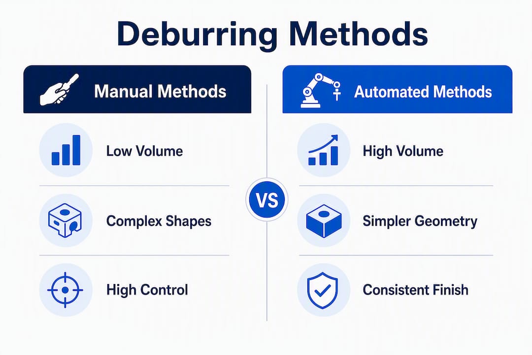
Mechanical deburring classification by volume and complexity confirms this mapping: manual methods suit small batches and complex geometries, while automated processes such as vibratory tumbling or robotic CNC brush systems address high-volume, consistent-finish requirements.
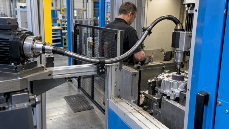
Flexible-shaft configurations are specifically suited to valve override internals, synchronization shafts, and flap actuation components, where rigid spindles cannot reach and edge integrity is critical.
What are the main mechanical deburring methods, and where does each excel?
Manual hand tools (files, stones, scrapers) offer maximum control for low-volume or rework operations. They preserve tolerances on ductile materials but are slow and operator-dependent.
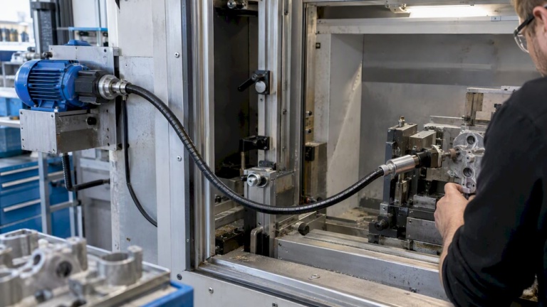
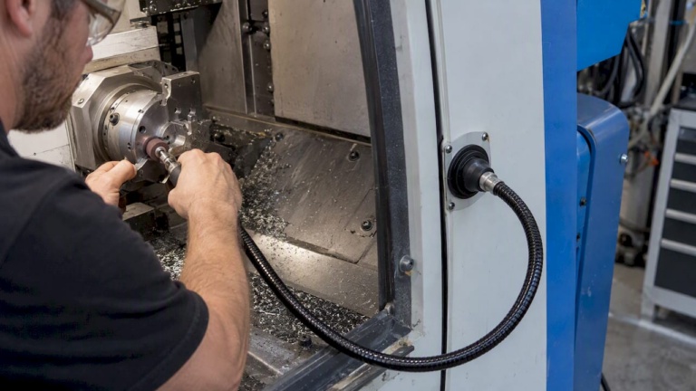
Flexible-shaft tooling with abrasive points, carbide burrs, or brush attachments reaches confined geometries that rigid spindles cannot access. Consistent tool pressure is achievable when feed and bend radius are controlled correctly.
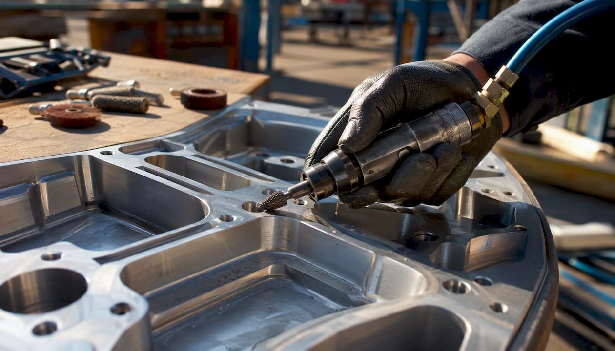
Die grinders and rotary tools are effective for medium-complexity parts. They remove material quickly but require skilled operators to avoid over-cutting on soft alloys.
Nylon and steel brushes work well on edges and external surfaces. Nylon brushes are gentler on aluminum and preserve tolerances; steel brushes suit harder alloys but can smear ductile materials.
Vibratory and centrifugal tumbling processes large batches uniformly. They are ineffective for micro-features or blind holes, where tooling cannot reach small slots.
Belt finishing handles flat or mildly contoured surfaces at high throughput. Edge rounding is predictable but not selective.
Robotic and automated brush systems deliver consistent results on high-volume parts with repeatable geometry. Integration cost is high; programming complexity increases with part variation.
Comparison of method categories
| Method category | Best for (volume) | Part complexity/access | Surface finish quality | Cycle time | Capex vs Opex | Material compatibility | Integration difficulty |
|---|---|---|---|---|---|---|---|
| Manual hand tools | Low | High / accessible | Good (operator-dependent) | Slow | Low capex, high opex | All metals | Minimal |
| Flexible-shaft tooling | Low–medium | High / confined | Good–excellent | Moderate | Low–medium capex | All metals, soft alloys | Low–moderate |
| Die grinder / rotary | Low–medium | Medium | Fair–good | Moderate | Low capex | Steel, aluminum | Low |
| Brush systems (manual) | Low–medium | Medium | Fair | Moderate | Low capex | Aluminum, stainless | Low |
| Vibratory / tumbling | High | Low / external only | Consistent, moderate | Fast (batch) | Medium–high capex | Most metals | Moderate |
| Belt finishing | High | Low / flat/contoured | Consistent | Fast | Medium capex | Steel, aluminum | Moderate |
| Robotic brush | High | Medium | Consistent, good | Fast | High capex | Most metals | High |
| Thermal / electrochemical | Medium–high | High / internal | Excellent on edges | Moderate | High capex | Conductive metals | High |
Aerospace-specific notes:
- Residual stress: aggressive grinding or forced removal can introduce tensile residual stress at edges, reducing fatigue life
- Edge integrity: tumbling rounds edges uniformly, which may conflict with drawing-specified edge-break tolerances
- Micro-feature safety: mass finishing is often ineffective for micro-features where tooling cannot reach small slots, as confirmed by Advanced Manufacturing research on micro-feature burr removal
How can process controls during machining reduce burr formation?
Reducing burrs at the source is the highest-return action for micro-features and high-precision parts. A smaller burr entering the finishing step means less material removal, lower risk of dimensional damage, and faster cycle times.
Practical controls include:
- Cutting-edge radius: A sharper edge shears material cleanly; a worn or radiused edge pushes material, forming larger burrs
- Feed per tooth: Reducing feed per tooth on the final pass lowers burr height on ductile materials
- Climb vs. conventional milling: Climb milling tends to produce smaller exit burrs on aluminum; conventional milling may be preferable on harder alloys to reduce tool deflection
- Cutter diameter and geometry: Larger cutter diameters reduce the chip-thickness ratio at exit, which can limit burr formation on through-features
- Coolant selection: Cryogenic cooling and minimum quantity lubrication (MQL) reduce cutting temperatures and tool wear, both of which contribute to burr formation; cryogenic minimum quantity lubrication (CMQL) extends tool life and improves edge condition
- Tool maintenance: A worn tool is the single most common cause of oversized burrs in production
For titanium and stainless steel, laser-assisted milling and ultrasonic vibration-assisted cutting reduce cutting forces and can prevent burr formation, reducing reliance on post-process finishing. In micro-machining, low-temperature machining with liquid CO2 has been used experimentally to reduce burr formation on very small features.
SME guidance, including work associated with LaRoux K. Gillespie, consistently recommends proactive process controls over force-heavy post-process removal for precision and micro-components.
Pro Tip: Invest engineering time in cutter geometry and feed optimization before specifying finishing automation. A 20% reduction in burr height at the machining stage can eliminate an entire finishing pass downstream.
What are the best practices for manual deburring in production or rework?
Manual deburring produces consistent results when workholding, abrasive selection, and technique are correct. Without secure fixturing, vibration causes irregular material removal and secondary burrs.
- Secure the workpiece in a vise with protective jaws (copper, aluminum, or plastic). Position the edge to be deburred parallel to the jaw faces at a comfortable working height.
- Select the correct file shape: flat file for straight edges, round file for holes, half-round for curved edges, square or pillar file for slots and keyways.
- Select cut grade by burr size: bastard cut for heavy burrs (castings, saw-cut edges); second cut (medium) for standard machined edges; smooth or dead smooth for finishing passes and precision work.
- File at 45° to the edge using forward-only strokes. Lift the file on the return stroke; dragging backward dulls the teeth and can damage the workpiece surface.
- Apply controlled, consistent pressure. The goal is to fatigue and snap the burr off at its base, not to force material away. Alternating light passes on opposing faces work-harden the burr until it fractures cleanly, as described in precision burr removal technique guidance.
- Inspect after every 2–3 strokes by running a fingernail carefully across the edge. For precision work, use a burr gauge or edge radius comparator.
- Finish with a smooth-cut file or fine abrasive stone to meet surface finish requirements and remove any scratches from the coarser cut.
Safety: Wear cut-resistant gloves when handling deburred parts. Use face protection with rotary tools. Never remove a part from the fixture until the tool has stopped completely.
Pro Tip: For a second-cut flat file on steel or aluminum, use forward-only strokes and overlap each stroke by one-third of the file width. This produces a uniform chamfer and prevents the tooth-loading that causes premature dulling.
How should deburred parts be inspected in aerospace production?
Inspection must include visual, tactile, and dimensional checks tied to drawing tolerances and assembly fit criteria. A burr present at measurement prevents accurate fixturing, causes off-center mounting, and increases downstream rejection costs, making inspection a mandatory gate before any assembly or metrology step.
Inspection checklist for deburred parts:
Visual check under angled lighting to reveal edge shadows from remaining burrs.
Tactile edge check with a fingernail or gloved finger across all deburred edges.
Magnified or optical microscope inspection for micro-features and tight-tolerance edges.
Go/no-go fixtures to confirm edge-break dimensions meet drawing callouts.
Sample caliper or profilometer measurements against acceptance criteria.
Documentation: sampling plan, nonconformance log, and routing decision (rework vs. scrap).
SME quality guidance frames deburring as a quality gate, not an aesthetic step. Seating errors from residual burrs cause alignment shifts that propagate through assembly stacks, particularly in flap actuation and valve override systems where dimensional tolerance chains are tight.
Parts that fail visual or tactile inspection route to rework if the burr is accessible and the parent material has dimensional margin. Parts where rework would violate a critical dimension route to scrap. Document both outcomes in the nonconformance log.
When do flexible-shaft drive solutions solve the deburring problem?
Flexible-shaft drive solutions are the preferred integration for precision finishing in confined or complex geometries where rigid spindles cannot reach. The shaft transmits torque and rotation around bends and through tight routing paths, delivering consistent tool speed and pressure at the working end regardless of the access constraint.
Key application scenarios:
- Valve override internals and actuator housings where straight-line tool access is blocked
- Flap and slat actuation components with internal edge-break requirements
- Synchronization shaft assemblies with intersecting bores
- Thrust reverser structures where edge integrity affects sealing and fatigue life
Integration checklist for machine builders:
- Specify required torque and RPM at the tool end, accounting for transmission losses through the shaft bend radius
- Define the minimum bend radius for the routing path; tighter bends reduce torque transmission efficiency
- Select coupling interfaces compatible with the tool attachment (collet, hex drive, or custom coupling)
- Confirm workholding alignment so tool pressure remains consistent across the full stroke
- Plan maintenance access for shaft inspection and replacement
Biax-flexwellen flexible shafts for precision deburring are configured for these requirements, with torque/RPM guidance and coupling options suited to aerospace finishing environments. For confined internal geometries, consistent feed and light pressure are critical to avoid smearing in ductile materials such as aluminum alloy.
Pro Tip: When routing a flexible shaft through a tight assembly, prototype the bend path with a dummy shaft before committing to fixture design. Actual torque loss through a compound bend is higher than single-bend calculations suggest.
What are the cost and throughput trade-offs across deburring methods?
Choose by the break-even of labor time versus machine throughput. Automated processes amortize capital cost on high volumes; manual methods remain cost-effective for low-volume and geometrically complex parts.
| Method category | Typical cycle time per part | Capex orientation | Suitable batch size |
|---|---|---|---|
| Manual hand tools | Minutes to tens of minutes | Very low | 1 part |
| Flexible-shaft assisted manual | Minutes | Low–medium | 1 part |
| Robotic / automated brush | Seconds to low minutes | High | high volume |
| Vibratory / centrifugal tumbling | Batch hours | Medium–high | high volume |
| Thermal / electrochemical | Minutes (plus setup) | High | medium volume |
Setup time, part handling, and fixture cost are often the dominant variables at medium volumes. Chemical and thermal methods add post-deburr cleaning or drying cycles that extend total process time and require waste-stream management for spent electrolyte or combustion byproducts. Cryogenic tumbling eliminates most liquid waste and can reduce operating costs for rubber and plastic components, but capital cost remains significant.
Key Takeaways
The most effective deburring strategy pairs process controls at the machining stage with the finishing method matched to production volume, part geometry, and access constraints.
| Point | Details |
|---|---|
| Match method to volume and geometry | Manual for low-volume or complex parts; automated tumbling or robotic brush for high-volume, simple geometry. |
| Reduce burrs at the source | Cutter geometry, feed-per-tooth control, and coolant selection lower burr height before finishing begins. |
| Enforce inspection gates | Visual, tactile, and dimensional checks must precede assembly and metrology to prevent seating errors and rejection costs. |
| Use flexible shafts for confined access | Flexible-shaft tooling reaches valve overrides, actuation components, and synchronization shafts where rigid spindles cannot. |
| Biax-flexwellen for precision integration | Biax-flexwellen supplies flexible-shaft configurations with torque/RPM guidance and coupling options for aerospace and precision deburring. |
The case for conservative deburring decisions in aerospace work
The instinct in production is to move fast through finishing. Deburring feels like a cleanup step, and the pressure to clear parts quickly is real. The evidence points the other way: the cost of a missed burr in an aerospace assembly, measured in rework, metrology error, and potential field failure, is substantially higher than the cost of a slower, more controlled finishing pass.
The conservative approach favors process controls first, minimal material removal second, and inspection before any assembly step. When a part has a tight tolerance on an edge-break dimension, the risk of over-deburring with an aggressive tool is as significant as the risk of leaving a burr. A smooth-cut file or a light flexible-shaft pass with a fine abrasive removes the burr without consuming the tolerance band.
The CAPEX versus throughput argument for automation is sound at volume. For low-volume aerospace rework or prototype builds, the investment in correct manual technique and a well-specified flexible-shaft setup often delivers better dimensional outcomes than a mass-finishing process that was designed for a different part geometry. Route to rework when dimensional margin exists; route to scrap when it does not. Document both. Inspection-led decisions protect the program.
Biax-flexwellen flexible-shaft solutions for precision deburring integration
Engineers specifying deburring for confined aerospace assemblies or precision machined components can contact Biax-flexwellen for application-specific flexible-shaft configurations. Biax-flexwellen supplies standard and custom flexible shafts with defined torque and RPM ratings, protective sheaths, and coupling interfaces suited to deburring, grinding, and polishing in tight or inaccessible spaces.
To prepare a technical inquiry, gather the following: required torque and RPM at the tool end, the bend routing path and minimum bend radius, the coupling interface at both the drive and tool ends, the operating environment (temperature, coolant exposure, contamination), and the target material and abrasive attachment type.
For engineers evaluating flexible-shaft drive solutions for machine integration or rework applications, Biax-flexwellen provides engineering guidance alongside standard components and bespoke configurations. Submit a technical inquiry via the BIAX contact page.
Useful sources and further reading
- Effective Burr Removal Techniques for Micro Features — Advanced Manufacturing: Primary reference for process controls on micro-features, including cryogenic cooling and laser-assisted milling for difficult materials.
- SME (Society of Manufacturing Engineers): Authoritative guidance on deburring as a quality gate and the case for proactive process controls over force-based post-process removal.
- Removal of Burrs — NMRI tutorial: Practical reference explaining why burrs must be removed before measurement and assembly, with fixturing and alignment implications.
- CNC Machining Burrs: Causes, Prevention and Deburring Methods — LK Prototype: Covers classification of deburring methods by production volume and part complexity, including thermal and electrochemical options for internal features.
- How to Deburr Metal — Benchmark Abrasives: Hands-on guidance for manual deburring technique, workholding, abrasive selection, and safety considerations.
- Flexible Shafts Enhance Precision Deburring — Biax-flexwellen: Application notes on flexible-shaft integration for confined-space finishing, torque/RPM considerations, and coupling selection.
Recommended
- How flexible shafts enhance precision deburring in manufacturing
- Machining Components Terminology: A Practical Engineer’s Guide
- The Role of Engineering Guidance in Manufacturing – BIAX Flexwellen
- Precision engineering terminology explained for manufacturing
Related Topics
Send your spec inquiry
Custom flexible shafts for your application — we quote within 1 working day.