Retrofit with Flexible Shafts: Engineering Guide for Installed Drives
11 November 2026A flexible shaft retrofit replaces or supplements a rigid drive path, a cardan arrangement or a gear train with a shaft that transmits rotation along a curved route. It is appropriate when the geometry of an installed machine or airframe-type assembly does not allow a straight line between drive and driven element. Success depends on four things: complete operating data, a bend radius that the shaft can sustain, correctly specified end connections, and a documented risk assessment of the modification.
This article covers the engineering sequence for such a retrofit. It addresses actuation and drive tasks of the kind found in thrust reverser systems, flap and slat actuation, valve override mechanisms and synchronization shafts, as well as industrial machinery. The focus is on functional principles, mechanical constraints and operating conditions.
TL;DR
- A flexible shaft retrofit suits installations where drive and driven element are offset, move relative to each other, or are separated by obstacles that a rigid shaft cannot pass.
- Collect torque (continuous and peak), speed, direction of rotation, length, routing, ambient conditions and duty cycle before any shaft is selected.
- Distribute bends over the greatest possible length, keep the routing static where feasible and avoid tight local radii at the end fittings.
- A modification to machinery in service requires a risk analysis. The method used for new machines can be applied, and EN ISO 13849-1 can support safety-related control design.
- Commission with a defined test: torque at the output, speed, temperature, run-out and noise, compared against acceptance criteria written before installation.
Table of Contents
- When a flexible shaft retrofit is appropriate
- Operating data to collect before specifying
- Selecting the shaft: torque, speed, length and bend radius
- Safety and regulatory framework in Germany and the EU
- Installation sequence
- Commissioning and acceptance criteria
- Inspection, lubrication and maintenance
- Perspective
- Product lines relevant to a retrofit
- FAQ
- Sources
When a flexible shaft retrofit is appropriate
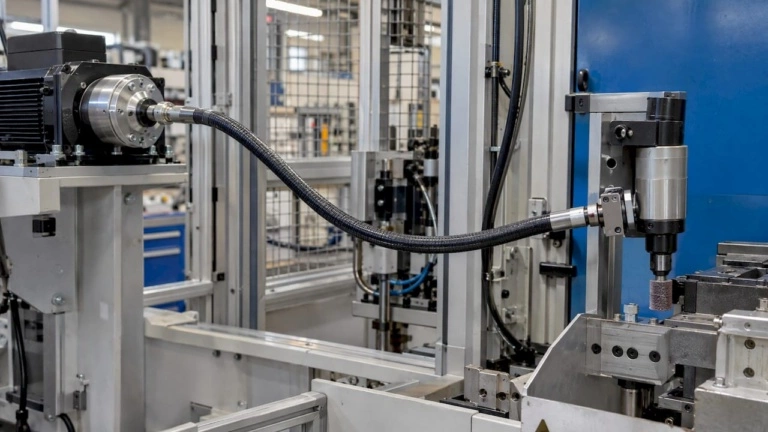
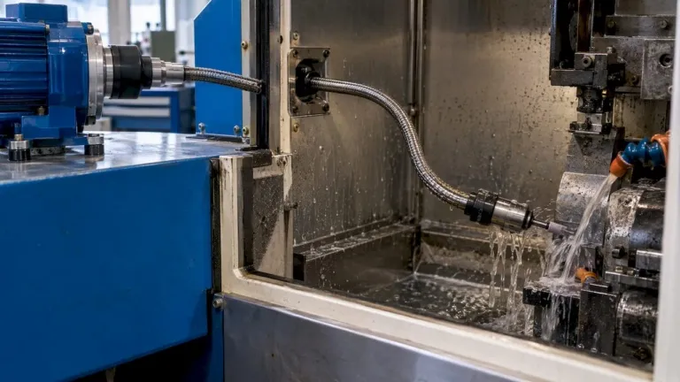
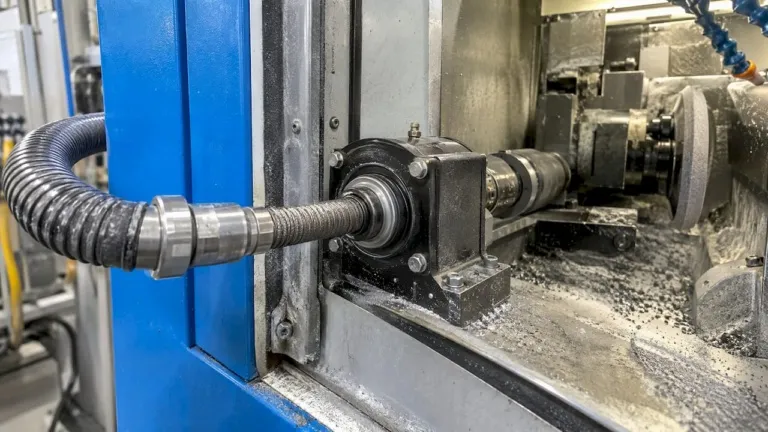
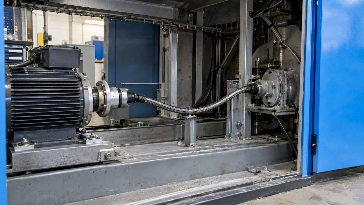
A flexible shaft consists of a wound wire core that carries torque, usually inside a protective sheath or casing that guides it and retains lubricant. The core rotates; the casing stays stationary. This allows the drive path to follow a curved route.
Retrofit cases fall into three groups:
- Relocation of the drive. A motor or actuator must sit away from the driven element because of space, heat, vibration or accessibility. A flexible shaft bridges the offset without a chain of universal joints and bearing supports.
- Replacement of a failed or obsolete drive path. A rigid shaft, angle gearbox or cable arrangement is no longer available or no longer fits revised surroundings. The flexible shaft is specified to the same torque and speed envelope.
- Added function. A manual override, a synchronization link between two actuators or a remote drive point is added to an existing system.
In aerospace-type installations, the typical functional roles are well established. Flap and slat systems use synchronization shafts so that actuation stays coordinated along a wing. Valve override systems use a shaft to move a valve manually or by a remote drive when the primary actuator is unavailable. Thrust reverser actuation distributes motion between several actuators. In each case the installation space is confined, routing is dictated by surrounding structure, and the shaft must meet defined torque and speed limits. Which regulations and approvals apply to a specific airframe or engine installation is a matter for the design organization responsible for that product.
A flexible shaft is less suited to tasks that need very high torsional stiffness over long distances or exact angular position without backlash compensation. The torsional windup of a wound core is part of the design and must be accounted for in the control concept. The selection guide on rigid versus flexible shafts sets out this decision in more detail.
Operating data to collect before specifying
Retrofit planning benefits from looking at the process in its environment. A trade article on structured retrofit planning recommends using FMEA to analyze critical process parameters and possible retrofit measures. The same logic applies to a single shaft: the data below should be recorded and, where possible, measured rather than taken from nameplates.
Load and speed
- Rated and peak torque at the driven element, including breakaway torque and any jam or stall condition the drive can produce.
- Operating speed range and the speed at which the shaft will spend most of its life. Speed and bend radius interact: a shaft that carries its rated torque in a straight line carries less when bent.
- Direction of rotation. Many flexible shafts transmit torque more favorably in one direction, because the winding tightens or loosens the layers. The direction must be fixed in the specification, and reversing duty needs separate attention.
- Duty cycle. Continuous, intermittent, or rarely used. A shaft used only for manual override sees very different loading from a synchronization shaft that rotates in every cycle.
Geometry
- Length between the end connections, measured along the actual route, not in a straight line.
- Bend radii and total bend angle, at every point of the route, with the smallest radius identified.
- Movement. Whether the route is fixed or one end moves, and by how much. Repeated flexing is a fatigue load that a static installation does not have.
- Available envelope for casing, clamps and end fittings, including access for later inspection.
Environment
- Temperature range at the shaft and at the end connections.
- Exposure to fluids, dust, vibration or contamination.
- Lubrication condition and any limits on lubricant type.
Interfaces
- Drive and driven shaft diameters, key or flat geometry, square or hex drives, or threaded couplings.
- Axial play and misalignment at both ends.
- Fixing method for the casing at each end.
The engineering overview on tool holder specifications covers torque, speed and bend radius together for aerospace-type tasks. A guide to motor control and flexible shaft limits explains how drive speed settings relate to shaft capability.
Selecting the shaft: torque, speed, length and bend radius
Torque and speed
Shaft capacity is a function of core construction, diameter and bend. Selection starts from the peak torque, not the average, with a margin appropriate to the consequence of failure. For safety-relevant functions such as override mechanisms, the margin and the failure mode should be defined in the design requirements, not left to catalog values.
Torsional windup also matters in synchronization. Where two shafts or actuators must stay in step, the angular deflection of each shaft under load should be calculated and compared with the allowable position difference.
Length and routing
Length increases windup and can raise friction in the casing. Shorter routes with gentle curvature are preferred. One practical rule from an older engineering forum discussion on installation is not cited here; the established principle is stated plainly: changes of direction should be distributed over as long a section of shaft as possible rather than concentrated in one tight bend.
In practice this means:
- Avoid bends directly at the end fittings. Provide a straight section of casing at each end.
- Do not exceed the minimum bend radius given for the shaft, and treat the minimum as a limit for static routing, not a design target.
- Avoid S-shaped routes with opposing curvature in close succession where an alternative exists.
- Support the casing with clamps at defined intervals so that it cannot move under vibration or whip under speed.
- Keep the route clear of hot surfaces, sharp edges and moving structure.
End connections
End connections transmit torque into the core and locate the casing. They are a common source of retrofit problems because the interface is rarely identical to the original. The points to define are the torque transfer geometry, the casing fixation, the axial position of the core relative to the casing, and the allowable misalignment. Drive and driven shafts should be concentric with the casing axis as closely as the installation permits, so that the first bend does not start inside the coupling.
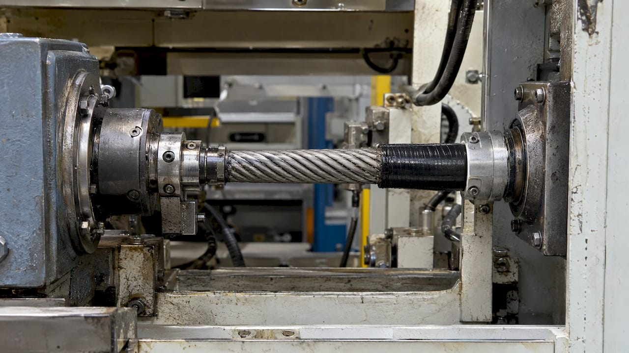
For non-standard interfaces, a custom configuration is usually more reliable than an adapter chain. Details on machine elements and flexible drives versus universal joints describe the options in this area.
Tool and attachment limits
Where the shaft drives a tool, the tool’s own limits apply. One tool supplier’s data for mounted flap wheels states that the indicated maximum speed must never be exceeded and the clamping length must be at least 15 mm. The same source notes that reducing contact pressure and peripheral speed, together with grinding oil, lowers tool wear and thermal load on flexible shafts. These figures concern abrasive tools specifically, but the principle carries over: the lowest speed limit in the chain governs.
Safety and regulatory framework in Germany and the EU
A flexible shaft retrofit is a modification of an existing system. Whether it is a substantial modification, and who carries which obligations, must be assessed per case.
Risk analysis for modifications
A technical guide from French authorities on substantial modification of machinery states that an employer modifying machinery in service must analyze the risks. It adds that the risk-assessment requirement of the Machinery Directive is not legally applicable to in-service machinery as such, although its method can be useful. For the analysis itself, the guide recommends a method comparable to that used for designing new machines, and notes that EN ISO 13849-1 can be used for the design of safety-related control systems. The guide is French and dates from 2014, so it serves as a method reference, not as a statement of current German law.
In practice the analysis should cover:
- New hazards created by the shaft itself: rotating core within the casing, whipping if the casing fails, and entanglement at exposed ends.
- Changes to the existing safety function, for example if the retrofit changes stopping time, overrun or the position of a mechanical stop.
- Effects of a shaft failure on the system: loss of drive, loss of synchronization, or uncontrolled motion.
- Guarding of exposed rotating parts, and the inspection access the guard must still allow.
Regulation change in 2027
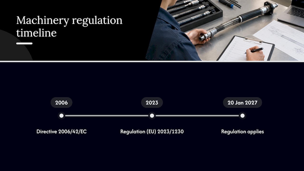
The EU Machinery Regulation (EU) 2023/1230 applies from 20 January 2027 and replaces the Machinery Directive 2006/42/EC. It defines substantial modification, which is relevant to any retrofit that changes the hazard situation of a machine. Operators and design engineers planning a retrofit that will be completed after that date should check the current text and the competent notified body or authority.
For aerospace products, airworthiness requirements and the approval path of the type certificate holder take precedence over machinery rules. Responsibility for compliance rests with the design organization.
Installation sequence
- Verify the data. Compare the specified torque, speed, direction and length against the as-built situation.
- Inspect the route. Check clearances, edges and heat sources, with the shaft in its extreme positions if the installation moves.
- Prepare the interfaces. Clean, deburr and measure drive and driven shafts. Check concentricity.
- Fit the casing first. Fix the casing at both ends and at the clamp points without forcing a tighter radius than planned.
- Insert or connect the core. Ensure the core seats fully in both end connections and that axial play is within specification.
- Check free rotation by hand where the design allows. Increased resistance indicates a bend that is too tight, misalignment or a pinched casing.
- Guard and mark exposed parts and record the installed routing with photographs or drawings for later inspection.
Commissioning and acceptance criteria
Acceptance criteria are best written before installation, in the same document as the specification. A practical set:
| Check | What is measured | Typical acceptance basis |
|---|---|---|
| Free rotation | Hand torque or no-load drive current | Within the value defined at design |
| Load torque | Output torque at rated and peak points | Meets requirement without exceeding shaft rating |
| Speed | Output speed over the working range | Within tolerance, no resonance range in operation |
| Temperature | Casing and end fitting temperature after a defined run | Below the limit for lubricant and sheath |
| Run-out and vibration | Visible whip, noise, vibration at the casing | No contact with surrounding structure |
| Synchronization | Angular difference between driven ends under load | Within the allowable position error |
| Function in fault case | Override or stop behavior | Matches the risk analysis |
The values in the last column come from the project’s own requirements; they are not universal. Record the results so that a later inspection has a reference.
Inspection, lubrication and maintenance
A retrofitted shaft should carry a maintenance plan from the day it is installed. The elements are:
- Visual inspection of the casing for kinks, abrasion, cracks or displacement of clamps.
- End connection check for play, loosening and wear at the coupling interface.
- Lubrication condition. Lubricant type, quantity and interval depend on speed, temperature and the shaft design. Shafts operating at high speed need particular attention; see the notes on flexible shaft lubrication above 10,000 rpm.
- Signs of wear or impending failure: rising drive current at the same load, new noise, heat at the casing, irregular rotation of the output, or lost synchronization.
- Intervals. Base them on duty cycle and consequence of failure. Rarely used override shafts should still be exercised and inspected on a fixed schedule.
A maintenance process for flexible shafts is documented separately. For shafts in finishing operations, the guide on grinding with flexible-shaft drives describes related operating practice.
Perspective
From our work with flexible shafts, the retrofit problems that recur are rarely about the shaft alone. They come from incomplete data on the load, from a route that was assumed instead of measured, and from an end connection that was adapted late in the project.
Our approach is to treat the shaft, casing and end connections as one defined drive element. Torque, speed, direction, length, bend radius and interface geometry are fixed together, so that the shaft is configured for the installation and not the installation bent around a catalog item.
This is the reason we support both standard components and custom configurations, including low-volume prototypes. A retrofit often needs one or a few units that match a specific interface, and a prototype run allows the commissioning checks above to be carried out before a series is released.
Uli
Product lines relevant to a retrofit
For retrofit work, BIAX offers several product lines. Actuation shafts are designed for manual or remote actuation tasks. Drive and tool shafts cover higher-speed drive applications. For interfaces and routes that no catalog item covers, special solutions and prototypes are configured to the stated torque, speed, coupling and design requirements. Technical inquiries should include the operating data listed above.
FAQ
Can a flexible shaft replace a rigid shaft in an existing installation?
Often yes, if the torque and speed are within the shaft’s rated capacity at the planned bend radius. Torsional windup and the direction of rotation must be checked against the control concept. The retrofit must also be assessed as a modification of the existing system.
Which data does a manufacturer need to specify a retrofit shaft?
Rated and peak torque, speed range, direction of rotation, route length, minimum bend radius, ambient temperature, duty cycle and the geometry of both end connections. Drawings or photographs of the route shorten the clarification. Movement of either end should be stated explicitly.
Is a risk analysis required for a retrofit?
An employer modifying machinery in service must analyze the risks, according to a French technical guide on substantial modification. The method used for new machines can serve as the basis. For aerospace products, the approval requirements of the responsible design organization also apply.
How often should a retrofitted flexible shaft be inspected?
The interval depends on duty cycle, speed and the consequence of failure, and should be set in the maintenance plan at commissioning. Shafts that are used rarely, such as override shafts, should still be inspected and exercised on a fixed schedule. Technical questions on a specific installation can be sent through the BIAX contact options.
Sources
- Mit Struktur in den Retrofit (kem.industrie.de)
- Technical Guide of 18 November 2014 on substantial modification of machinery
- Mounted flap wheel product data (Hoffmann Group)
- EU-Maschinenverordnung 2027 (mgmsys.de)
Recommended
- Flexible shaft guide: Engineering compact drive solutions
- Rigid vs flexible shafts: Selection guide for industrial drives
- How to implement flexible shaft drive solutions (2026)
- Flexible Shafts Maintain 85-95% Efficiency in Tight Spaces
Related Topics
Send your spec inquiry
Custom flexible shafts for your application — we quote within 1 working day.