Match Motor Control to Flexible Shaft Limits for Accurate Tool RPM
28 September 2026Yes, you can regulate driven-end RPM with a flexible shaft, but only within limits set by nominal torque, critical torque (helical buckling), bend radius and the chosen drive architecture. The main control levers are motor or controller selection, gearbox or CVT ratio and shaft diameter or conduit choice. Before committing to a layout, check minimum bend radius, peak torque margins and speed monitoring requirements, since these determine whether the regulated speed at the tool matches the speed commanded at the motor.
TL;DR:
- Maximum RPM is constrained by the shaft’s nominal and critical torque ratings, with helical buckling risking failure if torque exceeds limits.
- Tighter bend radii and unsupported spans increase hysteresis and torque limits, reducing speed accuracy and effective tool RPM.
- Shaft diameter, conduit choice, and routing geometry must be balanced to maintain speed fidelity, torque margins, and physical fit.
- Speed regulation is most precise with motor controllers, but elastic torsion causes lag, making output end sensors essential for accurate control.
- Custom shafts rated for high RPM can be engineered to specific application demands, including target torque, routing, and connector types.
Table of Contents
- How flexible shafts transmit torque and why that affects RPM control
- Key parameters that limit usable RPM
- Drive and control strategies for regulating output RPM
- Integration best practices for routing and coupling
- Sizing workflow for motor, gearbox and shaft selection
- Failure modes and commissioning checks for speed accuracy
- BIAX engineering support for custom shaft and drive configurations
- When flexible-shaft speed control is the right architecture
- Request engineering support for a custom flexible-shaft system
- Sources
- FAQ
How flexible shafts transmit torque and why that affects RPM control
A flexible shaft transmits torque through a wound wire core (often consisting of multiple layers of counter-wound coils) that twists elastically along its length. This coil structure behaves asymmetrically under load: it stiffens in one rotational direction and softens in the other, which introduces a small but measurable lag between input and output rotation under varying load.
Diameter, length and conduit selection govern torsional rigidity and, by extension, how faithfully output speed follows input speed. A longer shaft accumulates more angular deflection under the same torque, and a conduit around the core changes both stiffness and buckling resistance, which in turn shapes the achievable torque transmission at a given speed.
- Coil windings store torsional energy elastically, so sudden load changes appear at the driven end with a delay rather than instantly.
- Longer, thinner shafts twist more per unit torque, reducing speed-tracking accuracy under variable load.
- Conduits add torsional stiffness and buckling resistance, allowing more torque to pass at the same nominal diameter.
Because of this elastic behavior, speed control (holding a target RPM) and torque control (holding a target load) are not interchangeable strategies. A shaft optimized for steady speed under light, consistent load will behave differently under a torque-limited process like grinding, where load spikes can momentarily slow the driven end even with a constant motor command.
Key parameters that limit usable RPM
Every flexible shaft datasheet lists a nominal torque rating and a critical torque value related to helical buckling. Helical buckling occurs when torque exceeds the point at which the coil core loses its straight-line geometry and deforms into a corkscrew shape, a failure mode that is mechanical rather than thermal or electrical.
Adding a conduit around a flexible shaft increases its resistance to helical buckling and raises its nominal torque rating for a given diameter, according to research on torque-dense remote actuation. A thin-walled coil sheath with low bending stiffness but high torsional rigidity restrains extension of the core and pushes the critical torque threshold higher without requiring a larger shaft.
- Larger diameters raise torque capacity but also increase minimum bend radius, which constrains routing in confined installations.
- Efficiency losses of roughly 5 to 15 percent are typical across bends and supports, so RPM at the tool end is lower than RPM commanded at the motor.
- Reducing the number of supports and keeping curvature in a single plane preserves more of the input speed at the output.
Selecting shaft diameter is therefore a negotiation between torque headroom, RPM fidelity and the physical envelope available for routing.
Drive and control strategies for regulating output RPM
Speed regulation for a flexible-shaft system can be implemented at the motor, in the mechanical transmission, or across the system architecture as a whole.
- Motor-level control: a variable frequency drive (VFD) adjusts AC motor speed directly, PWM control with encoder feedback closes the loop on DC or brushless motors, and servo or BLDC controllers offer the tightest bandwidth for dynamic load changes.
- Mechanical control: fixed gearbox stages set a speed ratio, right-angle hypoid stages redirect torque into constrained geometries, and inline CVT or toroidal drives allow continuous ratio adjustment without changing motor speed.
- System architecture: a pooled controller drives multiple shafts from one motor and distribution gearbox, while per-actuator control, including per-shaft CVTs, gives each driven end an independently adjustable speed, an approach documented in patent literature on multi-actuator variable-speed systems.
Speed control suits processes needing consistent surface speed, such as polishing, while torque control suits processes where load must stay bounded, such as deburring on variable stock thickness. Running a shaft in speed-control mode against a stalling load accelerates fatigue at the coil core and at connector interfaces.
Integration best practices for routing and coupling
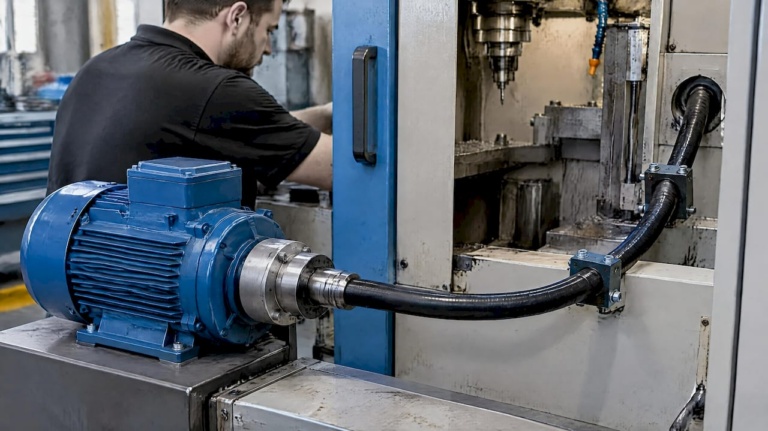
Installation geometry has as much influence on delivered speed as the shaft’s own rating. Routing in a single plane, rather than compound curves across multiple planes, keeps torsional behavior predictable and reduces hysteresis that would otherwise show up as speed inaccuracy at the tool.
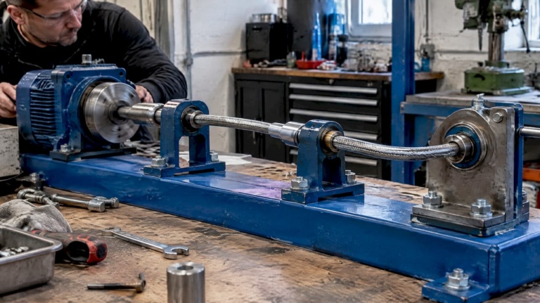
- Support the shaft at regular intervals recommended in the manufacturer’s installation drawing, since unsupported spans amplify whipping at higher RPM.
- Use a conduit sized for the application: it adds buckling resistance and lets a given shaft diameter carry more torque before failure, per the remote-actuation joint research.
- Select couplings against DIN 740 guidance, comparing rated torque, peak torque and vibratory torque to the coupling’s permissible limits.
- Verify connector interfaces, such as M14-threaded tool connections, seat fully and are torqued to the manufacturer’s specification before commissioning.
Pro Tip: Check peak torque and vibratory damping power against DIN 740 limits before finalizing a coupling, not after a field failure prompts a redesign.
Sizing workflow for motor, gearbox and shaft selection
A repeatable sizing sequence avoids mismatches between motor capability and shaft limits.
- Define the required output RPM and both continuous and peak torque at the tool interface.
- Choose a control mode (speed or torque) and select a motor and controller combination that covers the full motor-side operating envelope with margin.
- Set a gearbox or CVT ratio that maps the motor’s efficient operating range to the RPM and torque required at the shaft input.
- Select shaft diameter, conduit and minimum bend radius so nominal torque exceeds required torque with an appropriate safety factor, consistent with the design guidance for custom shaft configurations.
- Validate the assembly under dynamic loading, check for resonance near operating speed, and run commissioning tests before full deployment.
Each step constrains the next, so revisiting torque and RPM assumptions after step 4 is common when bend radius forces a smaller shaft than initially planned.
Failure modes and commissioning checks for speed accuracy
Most speed-regulation problems in flexible-shaft systems trace back to a handful of mechanical causes rather than controller error.
- Helical buckling from sustained overtorque, often worsened by tight bend radii that were not accounted for during sizing.
- Increased hysteresis from excessive or uneven bending, which shows up as lag between commanded and actual speed.
- Imbalance or runout in the shaft or connector, producing vibration that grows with RPM.
- Fatigue at connector threads or crimped fittings from repeated torque reversals.
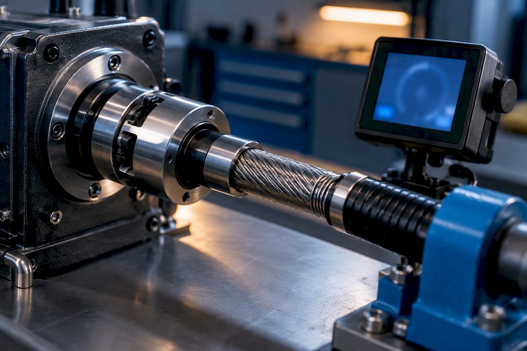
Instrumenting the system with a motor encoder, an inline torque sensor and temperature or vibration monitoring at the driven end catches these issues before they cause downtime. Commissioning should include speed and torque ramps across the full operating range, a resonance sweep to identify critical speeds, and a check that support spacing matches the installation drawing. When any of these tests reveal excess hysteresis or heat, derating RPM or moving to a larger shaft diameter is the appropriate response rather than adjusting the controller alone.
BIAX engineering support for custom shaft and drive configurations
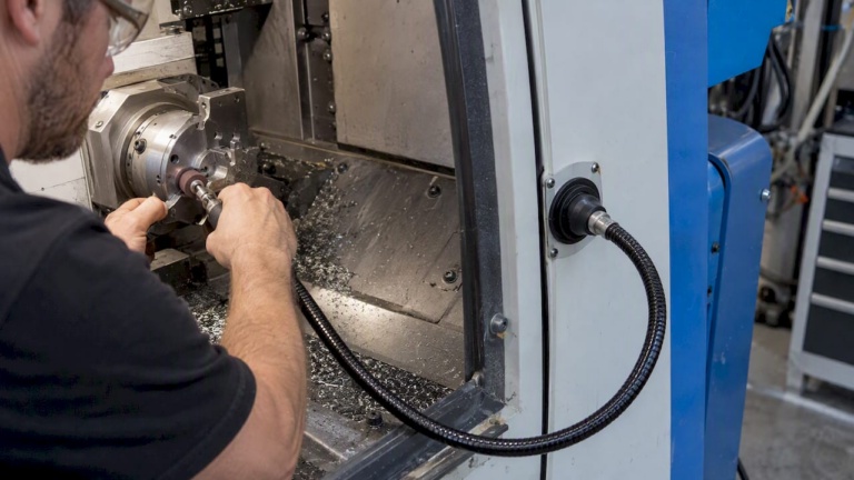
BIAX Flexwellen designs and manufactures standard and custom flexible shafts, including actuation shafts and drive components for applications where torque and rotation must reach confined or hard-to-access locations. Engineering support is available for machine builders and manufacturers working through the sizing and integration steps above.
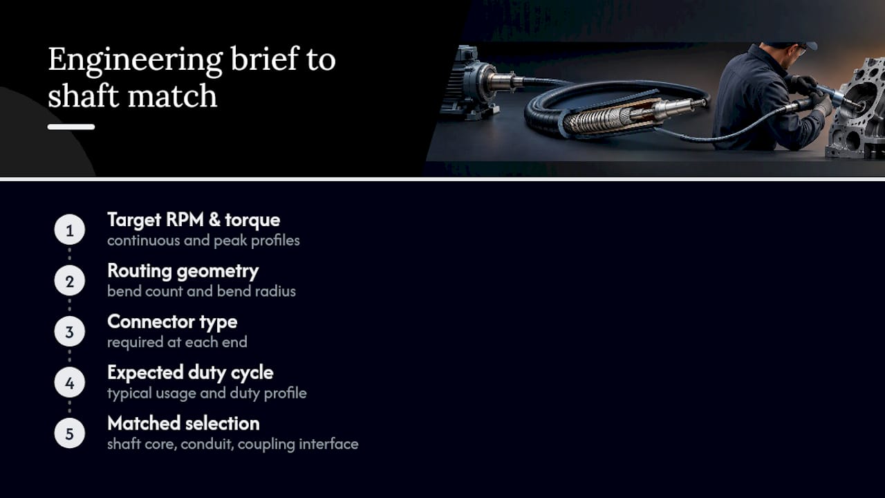
When preparing an engineering brief, engineers typically provide the target RPM and torque profile (continuous and peak), the routing geometry including bend count and radius, the connector type required at each end, and the expected duty cycle. This level of detail lets the shaft core, conduit and coupling interface be matched to the application rather than selected from a generic catalog entry. Requests can be directed through the custom flexible shaft configuration guide or submitted as a direct technical inquiry.
When flexible-shaft speed control is the right architecture
Flexible shafts earn their place when remote motor placement and compactness matter more than minimizing bend radius, such as in confined installation zones near thrust reverser mechanisms or flap and slat actuation linkages. They lose ground to belt drives or on-joint actuators when routing forces bend radii tight enough to erode torque margin. Sensorized shafts and variable-stiffness co-design, as explored in recent compliant-mechanism research, point toward tighter integration between mechanical design and control in future actuation systems.
— Uli
Request engineering support for a custom flexible-shaft system
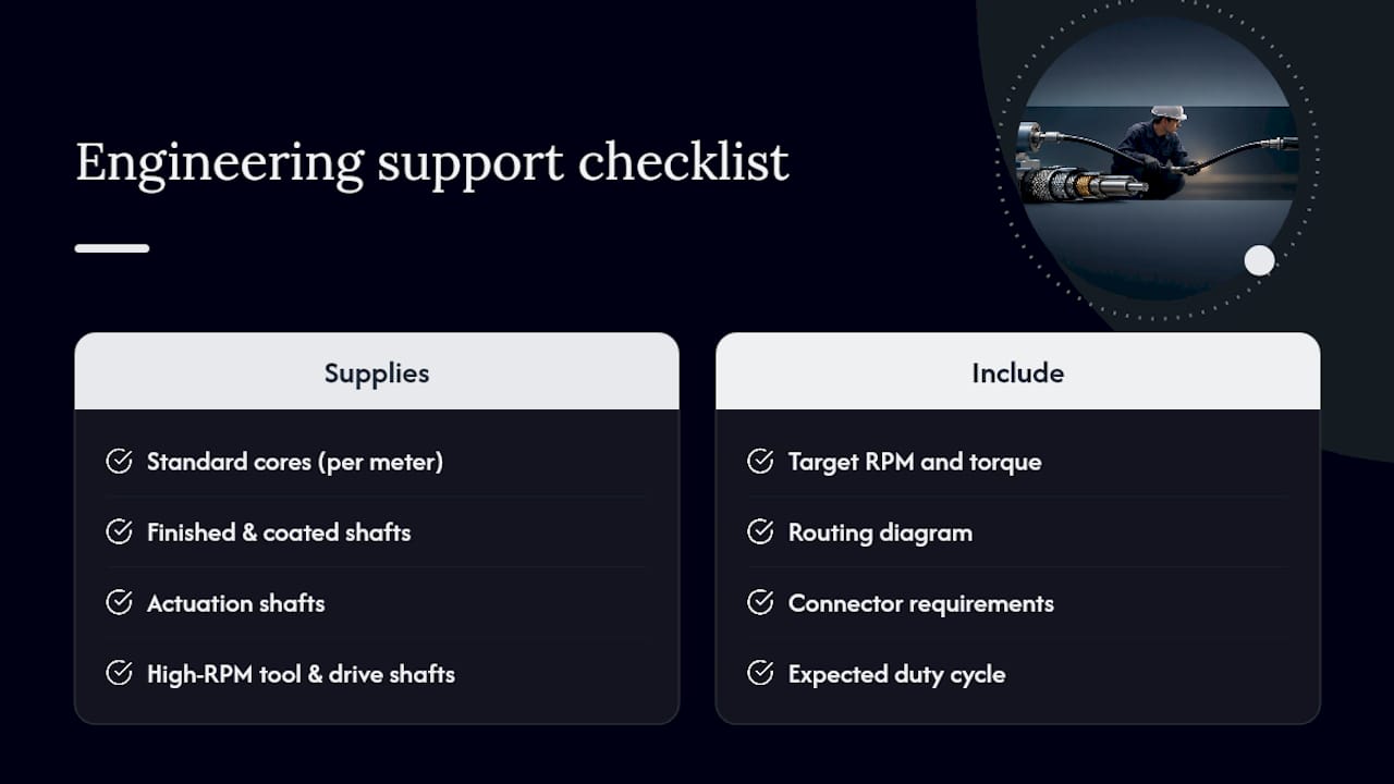
BIAX Flexwellen supplies standard cores by the meter, finished and coated shaft variants, actuation shafts, and tool and drive shafts rated for high RPM, along with custom solutions and prototype runs for low-volume projects. An engineering request is most useful when it includes the target RPM and torque, a routing diagram, connector requirements and the expected duty cycle. Review the Antriebs- und Werkzeugwellen range for high-speed tool shafts, or submit a technical inquiry through the BIAX contact page to start a configuration discussion.
Sources
Consult the torque-dense remote actuation paper for buckling and conduit behavior, DIN 740 coupling selection guidance for coupling checks, and the BIAX machine integration PDF for installation drawings and minimum bend radius examples.
- Design and Analysis of a Serial Position-Controlled Variable Stiffness Rotating Mechanism Based on Multi-Stage Torsional Compliant Mechanisms
- Actuator control system with individual variable speed control (patent excerpt)
FAQ
What determines the maximum RPM of a flexible shaft?
Maximum usable RPM is limited by the shaft’s nominal and critical torque ratings, its minimum bend radius, and how much torque the driven process demands at that speed. Exceeding critical torque risks helical buckling, so datasheets and installation drawings should be checked before setting a target speed.
Can you regulate speed on a flexible shaft the same way as on a rigid shaft?
Speed regulation works on a flexible shaft, but torsional elasticity in the coil core introduces lag and hysteresis that a rigid shaft does not have. Controllers and sensors should account for this by monitoring output-end speed rather than assuming it matches the motor command exactly.
How does bend radius affect torque and speed control?
Tighter bend radii increase hysteresis and reduce the torque a shaft can safely carry, which lowers the effective RPM available at the tool. Following the manufacturer’s minimum bend radius and single-plane routing recommendations preserves more of the input torque and speed at the output.
What sensors should be used to monitor flexible-shaft speed?
A motor encoder combined with an inline torque sensor gives the clearest picture of speed and load at the driven end. Adding temperature and vibration monitoring helps catch early signs of imbalance, runout or connector fatigue before they affect speed accuracy.
Does BIAX offer custom flexible shafts for speed-controlled applications?
Flexible shaft providers offer standard and custom shafts, including actuation shafts and tool and drive shafts, engineered to specified torque and RPM requirements. Engineers can submit routing geometry, torque profile and connector details through the BIAX contact page for a configuration review.
Recommended
- Flexible Shaft Design for Tight-Space Finishing Applications
- Torque, RPM, Bend Radius: Flex Shaft Tool Holder Specs for Aerospace
- Flexible Shafts for Tight Spaces: Boosting Precision
- How to Select Flexible Shafts for Precision Machinery
Related Topics
Send your spec inquiry
Custom flexible shafts for your application — we quote within 1 working day.