Surface Quality of Flexible Shafts: Specification and Function
23 October 2026Surface quality in connection with flexible shafts has two meanings. The first is the surface condition of the shaft components themselves: the core wires, the casing and the end fittings. The second is the surface that a flexible-shaft-driven tool produces on a workpiece. Both depend on defined parameters, a suitable measuring standard and a clear statement of the operating conditions. This article covers both, with emphasis on design constraints in aerospace and other confined installations.
TL;DR
- Surface texture is specified under the DIN EN ISO 21920 series, which replaced the earlier roughness standards. Drawings that still cite legacy notation need review.
- The lowest possible Ra is not the goal. A surface must retain a lubricant film and still limit abrasive wear.
- In a flexible shaft, surface condition at the core-to-casing contact governs friction, heat and fatigue life.
- Aerospace installations such as flap and slat drives, valve override systems and synchronization shafts add routing, temperature and verification requirements that should be stated in the specification.
- For finishing processes, the achievable workpiece surface depends on speed, tool, contact force and shaft routing, not on the shaft alone.
Table of Contents
- Where surface quality acts in a flexible shaft
- Specifying surface texture under ISO 21920
- Roughness and lubricant film: why smoother is not always better
- Aerospace installations: functional principles and constraints
- Surface quality produced by flexible-shaft-driven finishing
- Measuring and documenting
- Our perspective
- Relevant BIAX product lines
- FAQ
- Sources
Where surface quality acts in a flexible shaft
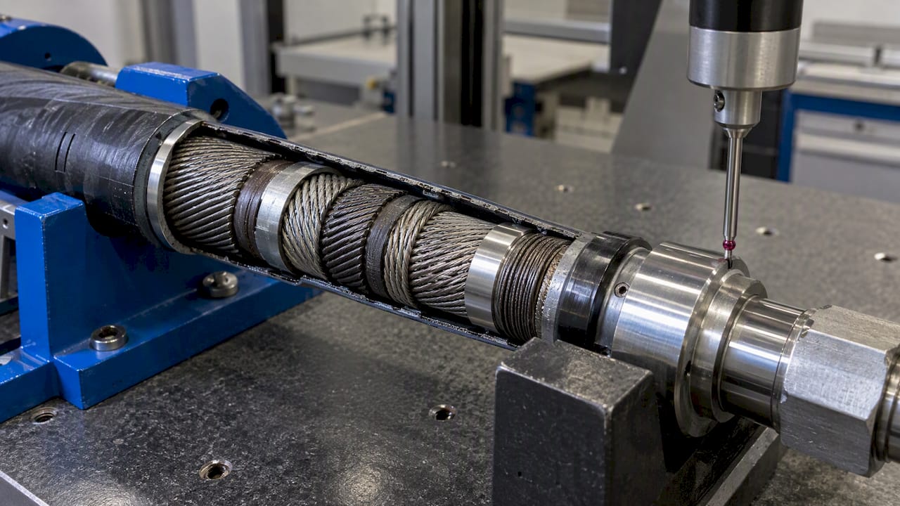
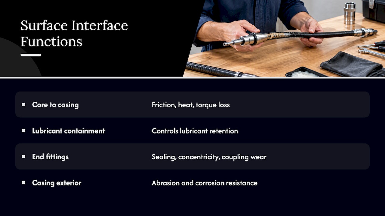
A flexible shaft is not a solid bar. It is a mechanism: a wound core that transmits torque, a casing or protective sheath that guides it, and end fittings that connect it to the drive and the driven element. Surface condition matters at several interfaces.
Core to casing. The core rotates and slides against the inner wall of the casing, particularly in bends. Wire surface, winding geometry and the inner casing surface determine friction. Friction produces heat and torque loss. In a long or tightly routed run, both accumulate.
Lubricant containment. Surface texture decides how much lubricant stays where it is needed. Research on flexible shaft lubrication describes the trade-off: excess grease raises the torque load, while insufficient lubrication leads to overheating and fatigue.
End fittings and couplings. Seats, shoulders and sealing surfaces on the fittings are conventional machined surfaces. Their roughness affects sealing, concentricity under load and wear at the coupling interface.
Exterior of the casing. Where the casing passes through brackets, clamps or bulkheads, its outer surface and any coating influence abrasion and corrosion resistance in service.
Each of these interfaces needs its own parameter set. A single roughness number on a general drawing note does not describe them.
Specifying surface texture under ISO 21920
The standards for profile roughness have changed. According to the Deutsche Gesellschaft für Qualität, the DIN EN ISO 21920 series replaced the previous standard for surface indications and the standards for terms, parameters and specification operators in December 2022. The PTB describes the three-part series as the successor to well-known standards such as ISO 4287.
For the designer, three practical consequences follow:
- Filtering differs. The new series uses robust Gaussian regression filters in accordance with ISO 16610-31, so values measured under the new rules are not automatically identical to legacy values on the same surface.
- Indications must be complete. A parameter without its filter settings, evaluation length and limit rule leaves room for interpretation between design, production and inspection.
- A short list of parameters is enough. Prof. Dr.-Ing. Dietmar Schorr writes about the new standard; the working recommendation drawn from his analysis is to define a limited set of parameters, roughly three to six, that reflect the functional requirement.
Profile parameters such as Ra and Rz remain the common basis. For complex or directional surfaces, areal parameters such as Sa and Sq describe the texture more completely. Polytec notes that roughness is only one component of a surface and that waviness and form can cause functional problems that roughness alone does not explain.
Example parameter structure
The table shows how a specification might be organized for the interfaces described above. The parameter choices are illustrative, not values for a specific product.
| Interface | Functional requirement | Typical specification content |
|---|---|---|
| Core-to-casing contact | Low friction, lubricant retention | Roughness parameter with filter and evaluation length, lay direction, lubricant type |
| Coupling seat | Concentricity, wear resistance | Roughness limit, form and run-out tolerance, hardness or coating |
| Sealing surface on fitting | Leak tightness | Roughness and profile parameters, no radial scoring |
| Casing exterior at clamps | Abrasion and corrosion resistance | Coating or finish designation, contact-point limits |
Numerical values belong in the drawing or the technical specification after the operating conditions are known. Generic values copied between projects are a frequent cause of rework.
Roughness and lubricant film: why smoother is not always better
A common assumption is that a lower Ra always improves a rotating interface. DK Fertigungstechnik states that surface quality determines how a component functions, and the underlying principle for rotating contacts is a balance. A surface that is too smooth may not hold a sufficient lubricant film. A surface that is too rough accelerates abrasive wear. The right range depends on rotational speed and load.
In a flexible shaft this balance has a thermal side. The ManufacturingTomorrow article cited above reports that a combination of dry film lubricant and grease, marketed under the name Flexcellent, lowered running temperature by roughly 25% compared with grease alone in the tests it describes. This is a finding about that lubrication method in that test series, not a general property of every flexible shaft. It does show that the lubricant system and the surface condition should be defined together.
Two design rules follow:
- Define the lubrication concept (grease, dry film, combination, lifetime lubrication) before fixing the roughness range of the contact surfaces.
- Verify at the specified bend radius and speed. Temperature and torque loss measured on a straight test run do not represent a routed installation.
Aerospace installations: functional principles and constraints
Flexible shafts are used in aerospace where rigid shafts, gear trains or universal joints cannot follow the available path. The following applications are typical examples for discussion. Specific requirements always come from the aircraft program, the system supplier and the certification basis, not from this article.
Thrust reverser systems
A thrust reverser actuation system must move its elements in a coordinated way. Flexible shafts are one means of linking actuators so that they run in synchronization over a routed path. Design constraints include the temperature range near the engine nacelle, vibration, and the need for predictable torque transfer over many cycles. Surface condition at the core-to-casing contact bears directly on friction stability across that temperature range.
Flap and slat actuation
High-lift systems transmit torque along the wing, with drive stations at several positions. Shafts in these systems must handle limited rotation angles, load reversal and long runs. Backlash, windup and friction are the key quantities. Windup in a flexible shaft depends on construction, so the specification should state the allowable angular deflection under a defined torque, and surface-related friction should be considered when interpreting efficiency figures.
Valve override systems
Manual or remote override of valves is an actuation task rather than a continuous-power task. A flexible actuation shaft carries torque or rotation from an accessible location to a valve that is difficult to reach. Infrequent operation changes the surface question: corrosion resistance, lubricant aging and stick-slip after long idle periods matter more than steady-state running temperature. Starting torque after storage is a useful acceptance criterion.
Synchronization shafts
Where two or more actuators must move together, shaft windup and friction differences between lines show up as asymmetry. Matched construction, identical routing radii and consistent surface and lubrication conditions reduce scatter between channels. The specification should state the permitted deviation between channels, not only the nominal torque.
Confined installation environments
Tight routing is the usual reason for choosing a flexible shaft. Smaller bend radii raise contact pressure between core and casing and increase heat generation. Designers typically define a minimum bend radius, limit the number of bends, avoid reverse bends close to fittings and keep the casing supported at defined intervals. BIAX describes these routing questions for tight-space applications, and the guidance on machining in hard-to-reach spaces covers access constraints in more detail.
Operating conditions to state
A specification for any of these applications should contain at least:
- rated and peak torque, and direction of rotation (one-way or reversing)
- speed range and duty cycle
- minimum bend radius and total bend angle along the route
- ambient temperature range and exposure to fluids
- required service life or number of cycles
- allowable windup, backlash and starting torque
- coupling interfaces at both ends
- verification method and documentation scope
Certification of an aerospace assembly is a matter for the system supplier and the applicable regulations. A shaft is generally assessed as part of the assembly, and the same principle appears in current discussion of ATEX applications only as a reminder to define the assembly boundary early.
Surface quality produced by flexible-shaft-driven finishing
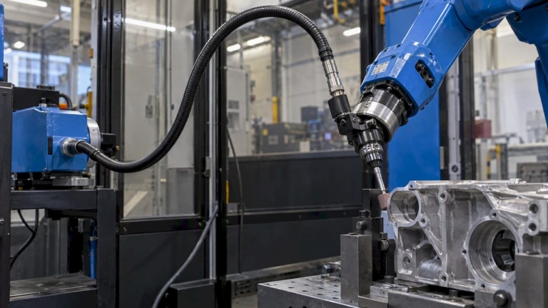
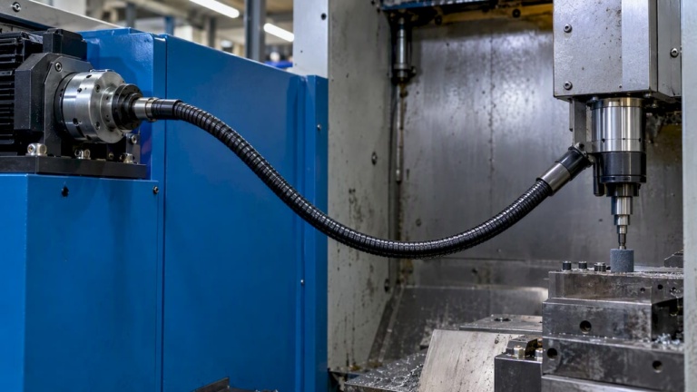
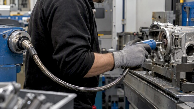
The second meaning of the keyword concerns the workpiece. Flexible shafts drive grinding, deburring and polishing tools in places where a rigid spindle cannot reach. The resulting surface depends on a set of variables:
- Speed. Tool speed sets cutting or abrasion behavior. Drive and tool shafts are available for speeds up to 50,000 rpm, as described on the drive and tool shaft page.
- Tool and abrasive. Grit, bond and tool geometry determine the texture and the lay of the finished surface.
- Contact force and feed. Variation in manual or robotic feed appears as variation in roughness.
- Shaft routing. Tight bends reduce torque at the tool and can cause speed fluctuation, which marks the surface.
- Vibration. Unbalanced tools or insufficient shaft support introduce chatter.
For aerospace parts, the requirement often includes edge condition, absence of burrs and a defined roughness in fillets and bores. The articles on process reliability in deburring and industrial polishing step by step describe the process steps. The page on selecting drive solutions for surface finishing lists the drive-side selection criteria.
A reproducible result requires that the process window be fixed: speed, force, tool life and routing. Surface measurement of the finished part, using the same ISO 21920 parameters as the drawing, closes the loop.
Measuring and documenting
Quality management needs one consistent method between drawing, process and inspection. HOMMEL ETAMIC provides information on how surface parameters under DIN EN ISO 21920 are applied in practice. Points to settle in the inspection plan:
- Which parameters and which filter settings apply to each surface.
- Where on the part and in which direction the measurement is taken.
- How many measurements and which acceptance rule apply.
- How old drawings with legacy notation are interpreted, and whether they are updated.
- Whether a profile measurement is sufficient or an areal measurement is required for the functional surface.
For flexible shaft cores, direct roughness measurement of wound wire is limited in practice. Functional verification, such as torque and temperature at defined bend radii, is often the more meaningful acceptance test.
Our perspective
In our experience with flexible shaft design, inquiries that mention only a roughness value usually lack what is needed to answer them. The more useful starting point is the function: torque, speed, bend radius, duty cycle and the coupling interfaces. From these we can discuss construction, casing, lubrication and the surface condition that belongs to them.
We also see that the surface of a flexible shaft is rarely the limiting factor alone. Routing, support spacing and lubrication concept usually have a larger effect on friction and service life, and they should be settled together. For finishing applications, we recommend defining the process window and the measuring method before comparing shaft options. Our work covers standard components as well as custom configurations and prototypes, and the core of it is matching the construction to the stated operating conditions.
— Uli
Relevant BIAX product lines
BIAX manufactures standard and custom flexible shafts. For actuation tasks such as valve override, the actuation shafts are the relevant line. For individual requirements and small batches, custom solutions and prototypes are available. Further guidance on parameters is in the article on selecting flexible shafts for precision machinery.
FAQ
Which standard applies to surface roughness specifications today?
The DIN EN ISO 21920 series applies to profile roughness indications and measurement. According to the DGQ, it replaced the previous indication standard and the related parameter standards in December 2022. Drawings that still use legacy notation should be checked for equivalent parameters and filter settings.
Is a lower Ra value always better for a flexible shaft?
No. A very smooth surface can fail to retain a lubricant film, and a rough one increases abrasive wear. The appropriate range depends on speed, load and the lubrication concept, so it should be defined from those conditions.
How does bend radius affect surface wear in a flexible shaft?
A smaller bend radius increases contact pressure between core and casing. This raises friction, heat and wear at the contact surfaces. A minimum bend radius and a limit on total bend angle should therefore be part of the specification.
What information is needed to request a flexible shaft for an actuation or synchronization task?
The most important data are torque, speed, duty cycle, routing with bend radii, temperature range, service life, allowable windup and the coupling interfaces. Drawings of the installation space help. Technical requests can be sent through the BIAX contact options on the main site.
Sources
- DGQ: ISO-GPS, Oberflächenbeschaffenheit / Rauheit (ISO 21920)
- PTB: Standards in the Roughness Measuring Techniques
- WOTech: Rauheit und Rauheitsmessung, was verändert sich durch die neue ISO 21920?
- Polytec: Leitfaden zur Messung der Oberflächenrauheit
- DK Fertigungstechnik: Oberflächengüte
- ManufacturingTomorrow: Testing Lubrication Methods to Prolong Life in Flexible Shafts
- HOMMEL ETAMIC: Oberflächenkenngrößen gemäß DIN EN ISO 21920 in der Praxis
Recommended
- How to Select Flexible Shafts for Precision Machinery
- For Engineers: Flexible Shaft Lubrication for Shafts Above 10,000 rpm
- Flexible shaft design for tight-space finishing applications
- How flexible shafts improve access for precision finishing
Related Topics
Send your spec inquiry
Custom flexible shafts for your application — we quote within 1 working day.