3 Exact Figures Vendors Need for Deburring Cell Flex Shafts
9 October 2026Use a flexible drive shaft when you must transmit rotation and torque in a confined or recessed work area where a rigid shaft or direct motor cannot be mounted. To size one, we need three things from you up front: continuous and peak torque, continuous and peak RPM, and routing data (length and minimum bending radius). We supply both standard and custom flexible shafts, including BIAX Flexwellen configurations built around these inputs, and we design to guidance such as ISO 14120 and BAuA guarding recommendations.
TL;DR:
- Give vendors continuous and peak torque and RPM separately, plus bend count, minimum radius, unsupported span, environment, fittings, runout tolerance, duty cycle, and service life.
- Choose a rigid extension or remote spindle for straight, accessible routes; flexible shafts lose torque, and long shafts near rated speed may need resonance checks.
- Apply ISO 14120 guarding and assess access and speed; BAuA guidance limits unguarded shaft end protrusion to about one quarter of its diameter.
- Because rotating cores face cyclic bending and steady torsion, request fatigue test results and a prototype when torque and speed approach limits before production.
Table of Contents
- Where flexible shafts fit in deburring and finishing work
- Specification checklist for your RFQ
- Integration checks: couplings, runout, and dynamic behavior
- Guarding and shaft-end safety requirements
- Fatigue and material considerations for long service life
- Requesting a custom shaft: what to send and what to expect back
- A specification engineer’s view on common mistakes
- Where to get flexible shafts and configuration support
- FAQ
- Sources
Where flexible shafts fit in deburring and finishing work
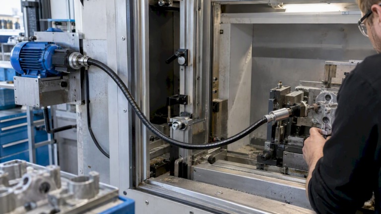
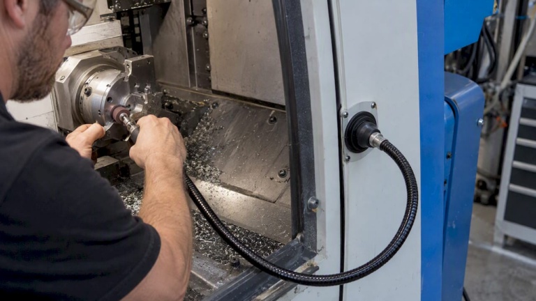
Flexible shafts earn their place wherever a straight-line drive cannot reach the work. Typical deployments include hand-held tool adapters for edge breaking, deburring inside recessed bores, finishing the interior of housings and manifolds, and routing torque through an articulated arm or fixture where a motor cannot be mounted directly on the spindle.
They are not the right choice for every confined-space problem. A rigid extension shaft or a remote spindle head may outperform a flexible shaft when the path is straight and access allows a stiffer, lower-maintenance drive. Compact gearboxes solve some reach problems without flexible transmission at all, though they add bulk the shaft avoids.
- Hand-held deburring and polishing tools fed from a remote motor.
- Bore and cavity finishing where the tool head must bend around an obstruction.
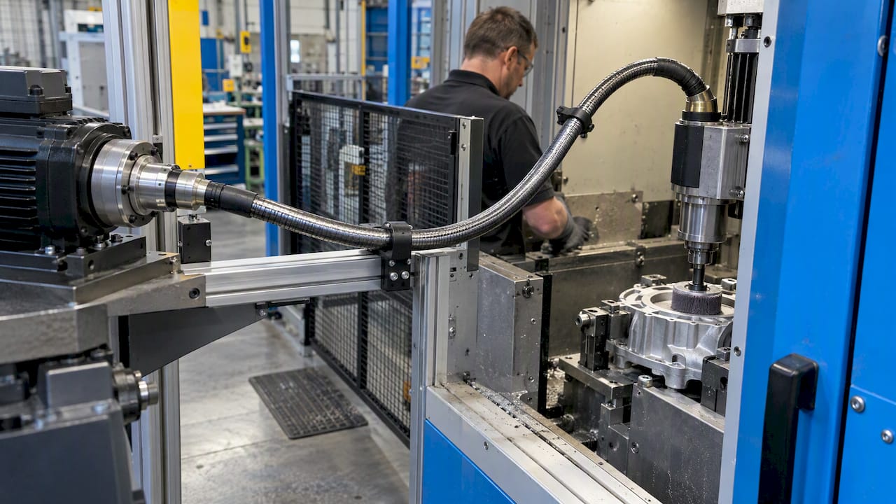
- Tool routing through robotic or fixture articulations in confined cells.
- Finishing inside enclosures where motor heat or size cannot be tolerated at the work point.
Efficiency losses in a well-specified flexible shaft typically stay in a moderate range depending on length, bend count, and load, so plan for some torque loss between motor and tool and size the driver accordingly. Our flexible shaft applications overview covers additional industry cases, and our efficiency and design guidance sets realistic expectations against rigid alternatives.
Specification checklist for your RFQ
A complete request for quotation prevents a vendor from guessing at the operating envelope. Include these items every time:
- Torque: continuous torque and peak torque, both in defined units, with the applied safety factor and expected duty cycle (percent on-time, cycle counts per shift).
- Speed: continuous RPM and maximum RPM, plus any transient speed profile such as start-stop cycling or momentary overspeed during tool engagement.
- Routing geometry: total installed length, number and angle of bends, minimum bending radius at each bend, and the longest unsupported span.
- Environment and sealing: exposure to coolant, dust, or elevated temperature, plus any sealing or protective sheath requirement.
- End fittings and tolerances: coupling or collet type at each end, required runout tolerance, and mounting orientation.
- Target service life: expected hours or cycles to failure, and the inspection interval you plan to apply once installed.
Torque and RPM numbers matter most, because fatigue behavior in rotating shafts depends on cyclic bending combined with steady torsion, and a vendor needs both continuous and peak values treated separately to select the right core construction and outer covering.
Pro Tip: Provide routing geometry and minimum bend radius before the first call: it lets a vendor return a usable efficiency estimate and temperature-rise expectation on the first pass instead of after several iterations.
Our tight-space design guidance walks through how routing choices affect the final specification.
Integration checks: couplings, runout, and dynamic behavior
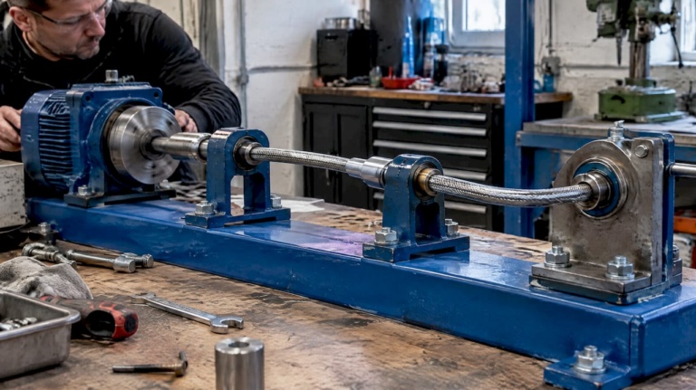
Coupling choice and installation geometry determine whether a correctly sized shaft actually performs as calculated. A shaft with the right torque rating can still underperform if the coupling introduces excess runout or if the installed route creates torsional lash under load.
- Match coupling type to the application: collet or clamp-style fittings generally hold concentricity better than simple set-screw hubs, which matters directly for runout-sensitive finishing tools.
- Verify retention under peak torque, not just continuous torque, since a coupling that holds at steady load can slip during transient spikes.
- Minimize unsupported span length and avoid tight reverse bends close together, both of which add torsional lash and accelerate wear.
- Request a critical-speed or modal check whenever the shaft is long relative to its diameter or runs near the upper end of its rated RPM, since whirl or resonance at operating speed can appear well below the shaft’s static torque limit.
Coupling standards such as ISO 10441 address flexible-element couplings that accommodate misalignment and are a useful reference when the mating hardware itself needs to absorb angular or parallel offset rather than the shaft alone.
Guarding and shaft-end safety requirements
Any rotating flexible shaft in a deburring or finishing cell needs a guarding review before installation, not after. ISO 14120 sets the general requirements for fixed and movable guards protecting personnel from mechanical hazards, and it is the standard to reference when specifying guard design for the rotating sections of the drive train.
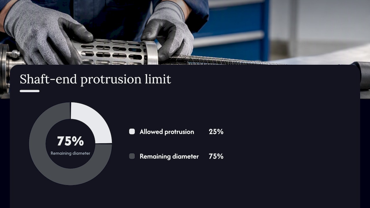
BAuA guidance notes that rotating shaft ends can be considered acceptably safe when they run true, present a smooth surface, and do not protrude beyond a limited fraction of their own diameter, with guarding and distance rules under DIN and ISO still applying on top of that.
A protrusion limit around a quarter of the shaft diameter is cited in BAuA’s practical heuristics for unguarded rotating ends, providing a dimensional guideline rather than a vague smoothness requirement.
- Confirm whether reduced operating speed, added guarding, or an interlock is required for your access pattern, or whether a smooth, non-protruding end treatment is sufficient.
- Label rotating sections clearly and restrict routine access to trained personnel only.
- Set an inspection frequency for guard integrity and shaft-end condition, not just for the shaft core itself.
Fatigue and material considerations for long service life
Flexible shaft cores see combined bending and torsion simultaneously: bending from the routed curve, torsion from transmitted torque. NASA’s technical analysis of shaft fatigue treats fatigue as the dominant failure mode for rotating shafts under this kind of cyclic loading, and recommends stress-life (S-N) data because fatigue life is inherently statistical rather than a single fixed number.
- Expect a size effect: larger-diameter core elements can show lower fatigue strength per unit stress than smaller ones, so derating with diameter is a legitimate design input, not a conservative guess.
- Surface finish and geometry matter as much as material choice: fillet radii, keyway edges, and any sharp transition act as stress concentrators that shorten fatigue life regardless of the base material’s rated strength.
- Apply a reliability or safety factor appropriate to your duty cycle, and request bench fatigue test data, including the cycle count and loading profile used, when the application runs continuously or at high cycle counts.
Pro Tip: When a design pushes close to rated torque and RPM simultaneously, ask for bench fatigue results rather than relying on calculated life alone: calculated numbers assume ideal surface finish and alignment that field installations rarely match exactly.
Our torque transmission explainer covers how core construction affects this balance in more depth.
Requesting a custom shaft: what to send and what to expect back
A clean RFQ gets a usable quote back on the first round. Paste these fields into your inquiry:
- Continuous torque, peak torque, continuous RPM, maximum RPM.
- Total length, bend count and angles, minimum bending radius, unsupported span.
- End fitting type and runout tolerance at each end.
- Environmental exposure (coolant, dust, temperature range).
- Target service life and quantity (prototype or production volume).
A credible supplier response includes an efficiency estimate for your specific routing, recommended support points along the span, an expected service life range, available test or validation options, and a lead time. When the application is new or runs at the edge of known limits, request a prototype or small-batch build for validation before committing to production volume. Our custom configuration guide outlines the data fields in more detail.
A specification engineer’s view on common mistakes
The most frequent error we see is treating peak torque and continuous torque as the same number, which leads to undersized cores that survive bench testing but fail early in the field. A close second is skipping a runout check at the coupling, since a shaft built to spec can still run rough if the mating hardware is loose.
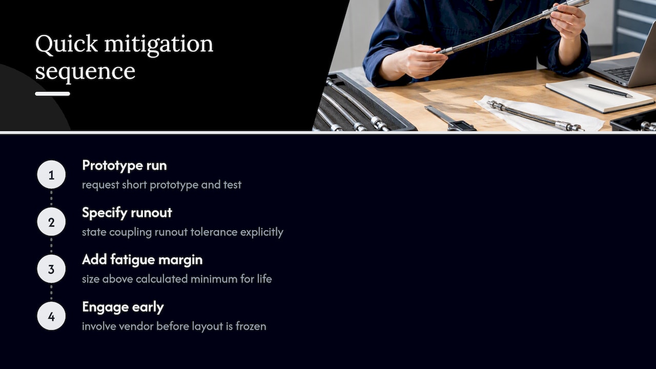
A quick mitigation sequence works well: request a short prototype run, specify runout tolerance explicitly, and build in a fatigue margin rather than sizing to the calculated minimum. Engaging a vendor before the layout is frozen, while bend radii and span lengths can still change, saves rework later.
— Uli
Where to get flexible shafts and configuration support
Flexible shaft cores are available by the meter for prototyping and custom lengths, finished tool and drive shafts rated for high-speed finishing work, and fully custom or small-batch builds for applications outside standard ranges. Providing the specification checklist above allows for configuration recommendations or prototype setup for validation before production volume commitment.
- Biegsame Wellen Meterware for standard-length cores and prototyping.
- Antriebs- und Werkzeugwellen for tool shafts rated up to 50,000 RPM.
- Sonderlösungen und Prototypen for custom builds and small-batch validation.
Reach our team through the BIAX contact page with your torque, RPM, and routing data and we will work through configuration options with you.
FAQ
What torque and RPM data do I need before contacting a vendor?
You need continuous torque, peak torque, continuous RPM, and maximum RPM, along with total shaft length, bend geometry, and minimum bending radius. Vendors use continuous and peak values separately to size the core and select the outer covering, since fatigue analysis treats steady torsion and cyclic bending as distinct loading inputs.
How do I know if a flexible shaft is the right choice over a rigid extension?
A flexible shaft fits when the drive path bends or when a motor cannot be mounted directly at the work point, while a rigid extension or remote spindle can outperform it on a straight, accessible path. The deciding factors are routing geometry and access, not torque alone.
What guarding is required around a rotating flexible shaft?
Guarding generally follows ISO 14120’s general requirements for fixed and movable guards, combined with shaft-end treatment guidance from BAuA on smooth, non-protruding ends. The exact guarding or interlock requirement depends on access pattern and operating speed.
What does a BIAX flexible shaft cost?
Pricing for custom and standard flexible shafts depends on core diameter, length, end fittings, and duty requirements, so it is available on request through our product pages and contact form rather than listed as a fixed figure.
How often should a flexible shaft be inspected once installed?
Inspection intervals depend on duty cycle and operating environment, so set them based on your target service life and the guard and shaft-end condition checks described in BAuA guidance. A shaft running near peak torque and RPM continuously warrants more frequent checks than one used intermittently at moderate load.
Sources
- BAuA — Kontrolliert bewegte ungeschützte Teile
- ISO 14120:2015 – Safety of machinery — Guards — General requirements for the design and construction of fixed and movable guards
- NASA technical report on shaft fatigue and sizing
Recommended
- Give These 4 RFQ Figures to Secure Flexible Shaft Couplings for OEMs
- How to Select Flexible Shafts for Precision Machinery
- How flexible shafts enhance precision deburring in manufacturing
- Remove Burrs in Manufacturing: A Practical Engineer’s Guide
Related Topics
Send your spec inquiry
Custom flexible shafts for your application — we quote within 1 working day.