Give These 4 RFQ Figures to Secure Flexible Shaft Couplings for OEMs
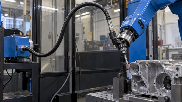
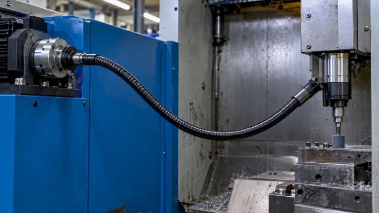
2 October 2026For confined-space finishing and machining tasks, flexible drive shafts are the correct mechanical component to specify, not rigid extension tooling or articulated arms. When requesting quotes, state four figures up front: continuous and peak torque in Nm, maximum RPM, minimum bend radius, and overall fitted length. Suppliers that cannot return calculations against all four are not ready to quote.
TL;DR:
- Flexible drive shafts are preferred over rigid extension tools for confined-space finishing and machining, with detailed torque, RPM, bend radius, and length specifications required upfront.
- Accurate routing drawings must specify the minimum bend radius, and supplier quotes should reflect installed routing conditions, not just bench test ratings.
- Torque capacity decreases with longer length and tighter bends, and higher RPM shafts need closer support, better lay construction, or factory balancing to prevent fatigue and resonance issues.
- Proper installation entails precise coupling tolerances, avoiding sharp bends, accounting for thermal expansion, and ensuring adequate guarding and dynamic testing before commissioning.
- Sealed sheaths, surface-treated core wires, and scheduled inspections are essential to address grit ingress, bending fatigue, and environmental wear, especially in abrasive or wet applications.
Table of Contents
- Quick selection checklist: copy-ready RFQ items
- Technical specification limits: torque, RPM, efficiency and bend radius explained
- Design and installation considerations: couplings, routing, mounting and guarding
- Materials and construction options: choosing core wires, sheaths and sealing
- Maintenance, life expectancy and testing to require from suppliers
- When to pick custom-engineered shafts vs off-the-shelf standard parts
- Practical engineering perspective: common specification mistakes and how to avoid them
- How BIAX Flexwellen supports specification and supply
- Sources
- FAQ
Quick selection checklist: copy-ready RFQ items
An RFQ that omits duty cycle or routing geometry produces quotes that cannot be compared on equal terms. State continuous torque and peak torque separately, along with the duty cycle (percentage on-time per hour) so the supplier can select a core construction rated for fatigue rather than static load alone. Specify RPM as a range, not a single figure, and state whether the application requires a balancing certificate or vibration report, since imbalance above a few thousand RPM becomes a bearing and coupling life issue.
Bend radius must be measured at the tightest point in the actual routing path, not assumed. Provide a routing sketch or CAD extract showing the minimum inside radius and the number of bends over the shaft length.
- State continuous torque, peak torque, and duty cycle together, never torque alone.
- Give RPM as a range and specify if balancing documentation is required.
- Report the minimum bend radius from the routing drawing, not a nominal value.
- List coupling interface details: shank diameter, drive type, and seating depth.
- Note environmental exposure (temperature range, coolant, grit) and any target cycle life or MTBF.
- Separate prototype quantities from production volumes and state required lead time and test deliverables.
Pro Tip: Attach the routing drawing to the RFQ itself rather than describing bend radius in text; suppliers size core wire diameter directly from that geometry.
Technical specification limits: torque, RPM, efficiency and bend radius explained
Torque capacity in a flexible shaft is not a fixed number. It decreases as length increases and as bend radius tightens, because the core wires experience combined torsional and bending stress at each curve. A shaft rated for a given torque at a 300 mm straight run will carry less at the same torque if routed through two 90 degree bends at a 150 mm radius. Tighter bends concentrate stress on the outer wires of the lay, which is why manufacturers publish derating curves rather than single torque values.
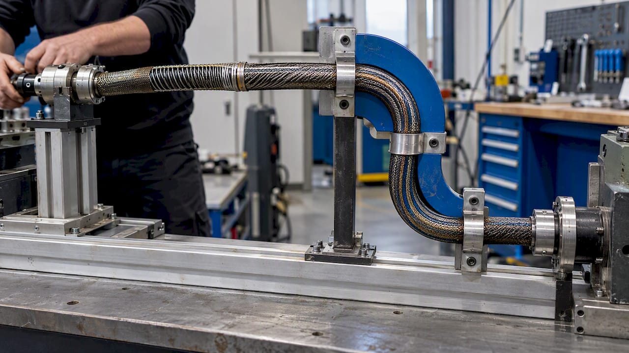
RPM limits follow a similar logic. Higher rotational speed increases centrifugal loading on the core and raises the risk of whip or resonance in unsupported spans, so shafts intended for higher RPM ranges typically need tighter lay construction, closer support spacing, or factory balancing.
Flexible drive shafts commonly lose measurable transmission efficiency over length and bend count, so supplier-quoted torque figures should already reflect the installed routing, not a straight-shaft bench test.
- Confirm whether quoted torque and RPM figures assume a straight bench test or the actual installed bend profile.
- Ask for a derating curve or table showing torque versus bend radius at the shaft’s expected length.
- Apply a higher safety factor for continuous duty than for intermittent or hand-tool use, and state the chosen factor in the purchase specification.
Design and installation considerations: couplings, routing, mounting and guarding
Installation errors, not material fatigue, cause most early flexible shaft failures. Coupling interfaces need explicit tolerances rather than nominal dimensions: shank diameter, keyway or flat orientation, and seating depth should all carry a tolerance band in the drawing package.
- Specify the coupling interface dimensionally, including shank diameter, drive type, and seating depth with tolerances.
- Route the shaft to avoid sharp bends near either end fitting, where stress concentration is highest.
- Specify clamp or support spacing along the length, particularly for higher RPM ranges or horizontal runs.
- Allow for thermal expansion in the routing path when the shaft operates near heat sources or in variable ambient conditions.
- Confirm guard and interlock requirements for any exposed rotating section, including safety switches that de-energize the drive when a guard is opened.
- Ask the supplier how the shaft behaves dynamically at full RPM in the actual installed bend profile, not just at the bench.
Pro Tip: Request a dynamic run-in report at installed RPM and routing before accepting a new shaft design into production.
Materials and construction options: choosing core wires, sheaths and sealing
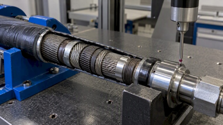
Core wire construction, sheath material, and sealing method together determine service life under a given combination of torque, RPM, and environmental exposure. A single-lay core suits lower torque, lower cycle applications, while multi-layer cores with alternating lay direction handle higher torque and reversing loads better because the layers share stress more evenly.
Sheath choice depends on the process environment rather than torque alone. Braided metal sheaths resist abrasion and higher temperatures, polymer or PTFE-lined sheaths reduce friction and weight for lighter duty, and hybrid constructions combine a metal outer braid with a low-friction liner for abrasive, wet processes such as grinding or polishing.
- Multi-layer, alternating-lay cores handle higher and reversing torque better than single-lay cores.
- Braided metal sheaths suit abrasive or higher-temperature environments; polymer or PTFE liners suit lighter, cleaner duty.
- Sealed end fittings and periodic grease lubrication are appropriate for wet or grit-heavy processes like deburring and polishing.
- Surface-treated or hardened core wires reduce wear at sustained higher RPM.
Suppliers offering surface-treated cores, such as BIAX’s Veredelte biegsame Wellen line, apply these treatments specifically to extend life at higher RPM or in abrasive service.
Maintenance, life expectancy and testing to require from suppliers
Flexible shafts wear through a combination of bend fatigue, abrasive ingress, and torque spikes, and the dominant failure mode depends on the application. In deburring and grinding environments, grit ingress into the sheath combined with repeated bending is typically the limiting factor on service life, which is why sealed sheaths and scheduled inspection intervals matter more than raw torque rating in those processes.
Ask any supplier for endurance cycle data and a documented run-in procedure before accepting a design into production; a shaft with no stated test basis carries unknown risk. Dual belt grinding machine technical documentation for abrasive finishing equipment illustrates the level of mechanical detail, such as adjustable belt speed and tensioning, that should accompany any drive component spec in these environments.
- Inspect sheaths for grit ingress and core wires for broken strands at defined intervals tied to duty cycle.
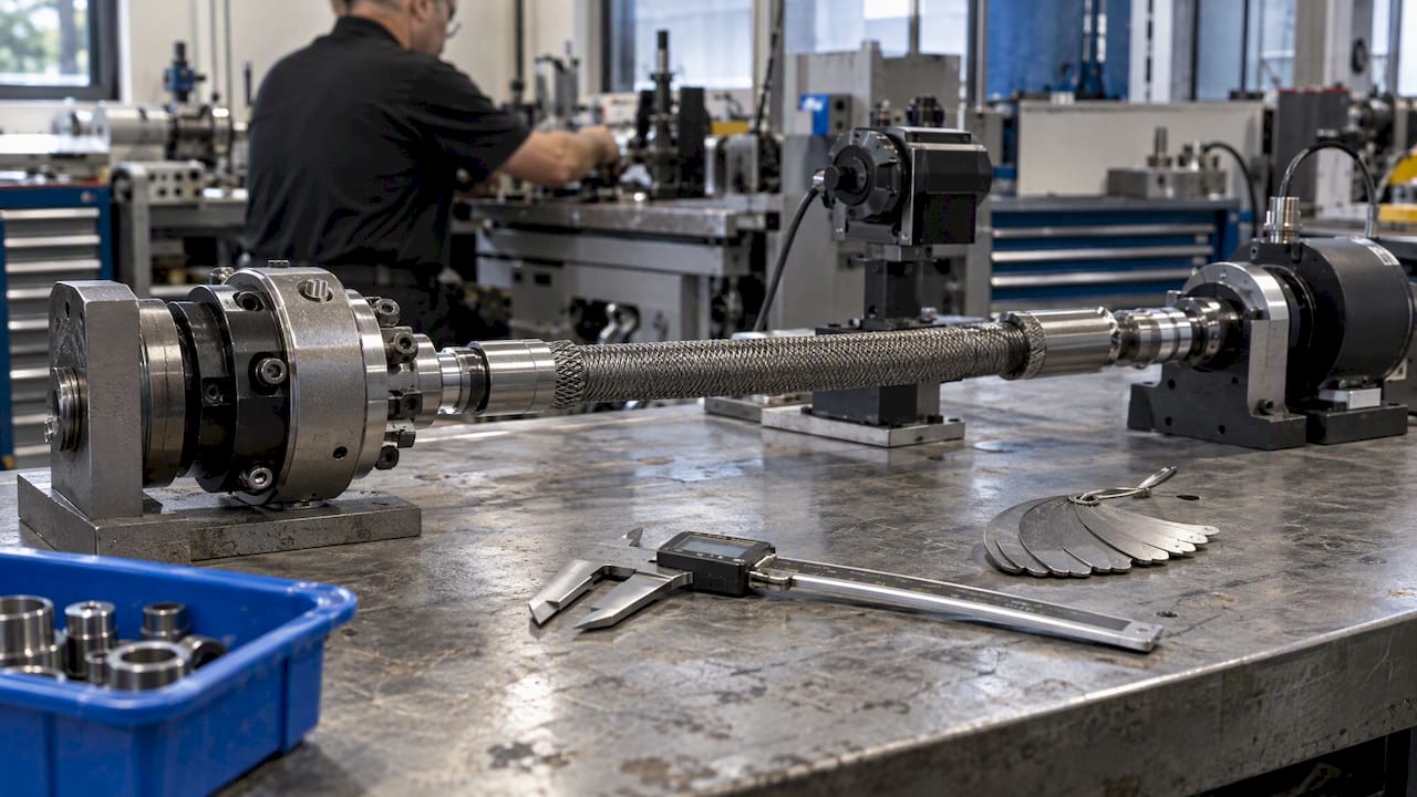
- Request torque endurance cycle data and a balancing report as standard acceptance documents.
- Define acceptance criteria (maximum allowable torque drop, vibration limits) in the inspection plan before first delivery.
- Track torque spikes and bend cycle counts, since these shorten life faster than steady-state running.
When to pick custom-engineered shafts vs off-the-shelf standard parts
Standard flexible shafts cover most straightforward torque and RPM combinations. Custom engineering becomes the right call when the application falls outside catalog ranges or carries constraints that a standard part cannot meet.
- Choose custom when torque and RPM fall outside published standard ranges, or when the combination is unusual for the shaft length.
- Choose custom when routing is constrained to a tight bend radius that standard parts are not rated for.
- Choose custom for aerospace-adjacent uses such as flap and slat actuation, thrust reverser mechanisms, valve override systems, or synchronization shafts, where certification paperwork and defined lifecycle targets apply.
- Choose custom for low-volume prototype runs where a standard part is close but not exact.
- Provide the manufacturer with torque and RPM targets, the full bend profile, target cycle life, and tool or drive interface dimensions to start an engineering review.
BIAX’s Sonderlösungen und Prototypen line covers this custom and small-batch engineering path, from prototype quantities through series production.
Practical engineering perspective: common specification mistakes and how to avoid them
The most frequent error is specifying bend radius as a nominal design value rather than the measured minimum at the tightest point in the actual routing path. That gap produces early core fatigue that only shows up after installation. During design review, pull the minimum radius directly from the routing drawing, never from memory, and confirm it against the supplier’s derating curve before releasing the purchase order.
— Uli
How BIAX Flexwellen supports specification and supply
BIAX Flexwellen designs and manufactures both standard and custom flexible shafts for industrial finishing and machining applications, and supports machine builders with engineering review during specification rather than after a failure. The product range spans raw flexible shaft meterware for standard integration, Betätigungswellen for actuation tasks, and Antriebs- und Werkzeugwellen for higher RPM tool drive applications.
Before contacting BIAX for a quote, prepare:
- Continuous and peak torque, with duty cycle.
- RPM range and balancing requirements.
- Minimum bend radius from the actual routing drawing.
- Coupling interface dimensions and tolerances.
- Target cycle life and environmental exposure.
Submit these figures through the BIAX contact page to start an engineering review for a standard or custom shaft configuration.
Sources
The dual belt grinding machine technical PDF documents belt speed, tensioning, and guarding practices relevant to abrasive finishing environments. BIAX’s custom flexible shaft design guide covers the engineering process for bespoke shaft configurations in further detail.
- Doppelband-Schleifmaschine Type DBS (Dual belt grinding machine) — technical PDF
FAQ
What torque and RPM figures should I include in a flexible shaft RFQ?
State continuous torque, peak torque, duty cycle, and an RPM range rather than a single RPM value. Suppliers size core wire diameter and lay construction from these figures combined with the routing profile, so incomplete data produces non-comparable quotes.
How does bend radius affect flexible shaft torque capacity?
Tighter bend radii concentrate stress on the outer core wires, which lowers the torque a shaft can safely carry compared to a straight run of the same length. Always report the minimum radius measured from the actual routing drawing, not a nominal design figure.
When should I request a custom flexible shaft instead of a standard part?
Custom engineering is the right choice when torque, RPM, or bend radius requirements fall outside standard catalog ranges, or when the application involves aerospace-adjacent uses like actuation or synchronization shafts with defined lifecycle and certification needs. Standard parts remain appropriate for straightforward torque and RPM combinations within published ranges.
What causes most flexible shaft failures in finishing applications?
In abrasive processes like deburring and grinding, grit ingress into the sheath combined with repeated bending cycles is typically the dominant life-limiting factor rather than raw torque overload. Sealed sheaths and scheduled inspection intervals address this directly.
What testing should a supplier provide before a flexible shaft goes into production?
Request torque endurance cycle data, a balancing report where RPM is significant, and a documented run-in procedure at the installed bend profile and RPM. These deliverables let you set acceptance criteria before the shaft enters regular production use.
Recommended
- 3 Flexible Shaft Connection Dimensions Engineers Must Specify
- Custom Flexible Shaft Configuration Guide for Engineers
- How to Select Flexible Shafts for Precision Machinery
- 4 Checks OEM Engineers Must Run for Axial Thrust in Flexible Shafts
Related Topics
Send your spec inquiry
Custom flexible shafts for your application — we quote within 1 working day.