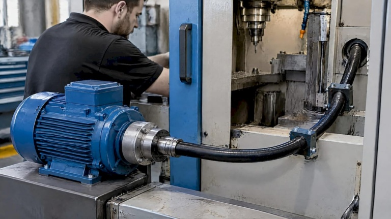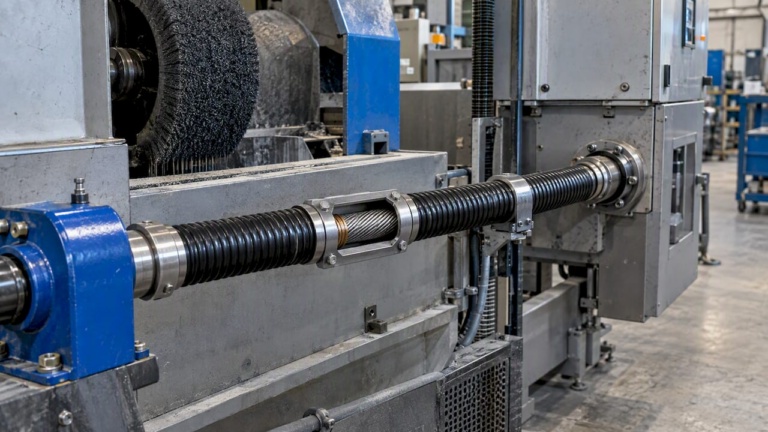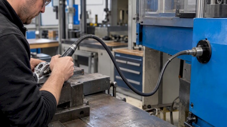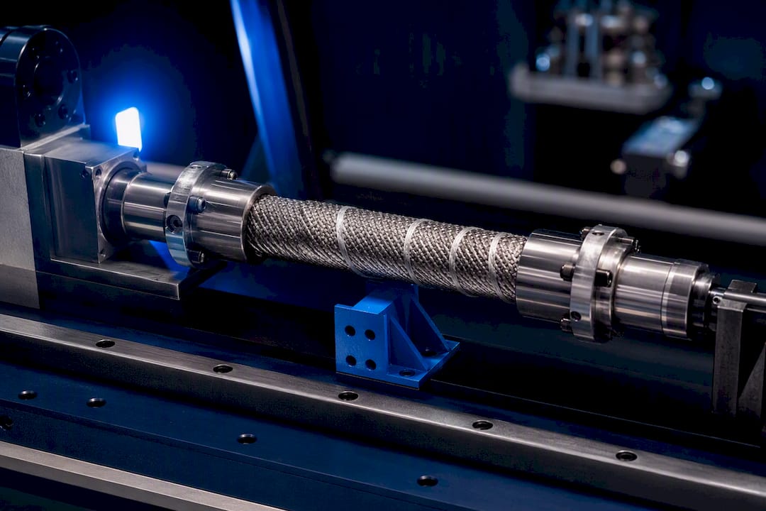
4 Checks OEM Engineers Must Run for Axial Thrust in Flexible Shafts
14 September 2026Axial forces are a primary design concern for flexible shafts whenever helical gearing, angled installation, or end-thrust reactions are present in the drivetrain. Before specifying a shaft, confirm the allowable axial end load from the motor or gearbox datasheet, check whether helical gears or other thrust sources feed axial load into the assembly, and determine if axial stops are needed at the shaft ends. Remember that torsional compliance in a flexible shaft reduces positional fidelity between motor input and output load, a factor that compounds when axial loading also shifts bearing preload. Engineering support can help validate these parameters against your application envelope.
TL;DR:
- Axial loads in flexible shafts mainly originate from helical gear thrusts, angled installation geometry, and reactions from driven components pressing along the shaft’s axis.
- Axial reaction forces often exceed motor or gearbox specifications if not properly calculated, requiring review of peak and typical loads during design.
- Torsional compliance and axial preload shifts can degrade positional accuracy and cause bearing preload drift, especially under cycling axial forces.
- Using FEA or multi-body simulation is necessary when torsion, axial load, and bending interact simultaneously or when complex geometries and dynamic effects are involved.
- Engineering support from specialized suppliers can optimize shaft design by validating axial load capacity and customizing configurations based on real operating conditions.
Table of Contents
- What Are Axial Forces in a Flexwelle and How Do They Arise?
- How Do Axial Loads Affect Bearings, Couplings, and Position Control?
- Hand Calculations, FEA, or Multi-Body Simulation: Which Do You Need?
- Design Mitigations and a Specification Checklist for Axial Loading
- Where Axial Forces on Flex Shafts Matter Most in Aerospace and Robotics
- How Do Temperature Changes Affect Axial Load Handling in a Flexwelle?
- Balancing Packaging Freedom Against Axial-Load Robustness
- Get Engineering Support for Custom Flexible Shaft Configurations
- Sources
- FAQ
What Are Axial Forces in a Flexwelle and How Do They Arise?
Axial forces in a flexwelle are loads acting along the shaft’s rotational axis rather than perpendicular to it. They arise from three main sources: helical gear meshes (which generate thrust proportional to the gear’s helix angle), angled or offset installation geometry, and end reactions from tooling or driven components pressing back against the shaft.
The core mechanics governing a flexible shaft’s response to torque follow classical torsion theory. For a uniform circular shaft, the torque-twist relation is T = G·J·(dφ/dx), and integrating over a length ℓ gives the angle of twist φ = Tℓ/(GJ), as detailed in MIT’s Unified Engineering torsion notes. Two terms drive this relationship:
- Polar moment of inertia (J): a geometric property describing resistance to torsion, dependent on cross-section shape and radius.
- Shear modulus (G): a material property describing stiffness under shear stress, typically given in GPa or psi.
Shear stress varies linearly with radius in solid or hollow circular shafts, which is why the classical formulas apply cleanly to round cross-sections. Non-circular sections behave differently. They can experience warping under torsion, and Wikipedia’s overview of torsion mechanics) notes that these geometries often require finite element analysis rather than closed-form equations. A flexwelle’s helical-wound core construction sits closer to the circular idealization than a keyed shaft with flats or splines, which is one reason the classical torque-twist model remains a useful first approximation even for compliant, multi-strand shaft cores.
How Do Axial Loads Affect Bearings, Couplings, and Position Control?
Axial thrust does not stay contained at its source. A helical gear mesh, for instance, pushes axial load directly into the supporting bearing and, depending on the drivetrain layout, back into the motor shaft itself. Motor manufacturers specify hard limits for this. Siemens SIMOTICS 1FT2 project documentation lists maximum permissible axial forces on the shaft end and explicitly warns against mounting a direct helical-gear pinion on the motor shaft when the resulting thrust would exceed those axial force limits. That warning generalizes well beyond one motor family: any driven component that introduces axial thrust needs its reaction path traced back to a bearing or thrust surface rated for it.
Flexible shafts add a second complication: torsional stiffness is not always uniform in both rotational directions. Manufacturing asymmetry in wound-core construction can produce direction-dependent stiffness, meaning the shaft twists slightly differently under clockwise versus counterclockwise load. Combined with axial preload shifts, this affects positional accuracy in closed-loop systems that assume a fixed torque-to-angle relationship.
Watch for these degradation patterns in service:
- Bearing preload drift from cumulative axial cycling.
- Coupling wear at contact points where axial float was not designed in.
- Positional lag in servo-controlled end effectors as torsional and axial compliance interact.
- Localized wear on shaft-end fittings under repeated thrust reversal.
Pro Tip: Instrument a prototype with a load cell at the bearing housing before finalizing coupling selection. Axial reaction forces measured under real duty cycles almost always differ from first-pass hand calculations, especially once thermal expansion is factored in.
Hand Calculations, FEA, or Multi-Body Simulation: Which Do You Need?
A structured verification sequence keeps analysis effort proportional to risk:
- Compute baseline torsional properties. Calculate J, confirm G for the core material, and solve φ = Tℓ/(GJ) to establish expected angle of twist under rated torque.
- Calculate axial reaction at bearings. Use gear thrust equations or manufacturer thrust coefficients to estimate the axial load transmitted to each support, then compare against the motor or gearbox datasheet’s allowable axial force.
- Check static and fatigue limits. Confirm the shaft core and end fittings tolerate combined torsional and axial stress across the expected duty cycle, not just at peak load.
- Escalate to FEA or multi-body simulation when torsion, axial load, and bending interact simultaneously, when the cross-section is non-circular or warping-prone, or when dynamic coupling between shaft compliance and system control loops needs modeling.
The MathWorks Flexible Shaft block supports this escalation path directly. It models torsional and bending compliance and offers four parameterization methods: by stiffness and inertia, by material and geometry, by segment stiffness, or by material and segment geometry.
| Modeling approach | Best suited for | Key inputs required |
|---|---|---|
| Hand calculation (T = GJ dφ/dx) | Preliminary sizing, single-load-case checks | J, G, torque, length |
| Lumped-mass parameterization | Quick dynamic checks, coarse system models | Segment mass, stiffness estimates |
| Eigenmode parameterization | Reduced-order models for faster simulation | Modal stiffness and inertia per segment |
| Full FEA / multi-body | Combined torsion, axial, bending; complex geometry | Segment-by-segment stiffness, boundary conditions |
Segment-by-segment stiffness and inertia values, rather than a single homogenized figure, generally produce more accurate dynamic behavior, particularly where intermediate supports or nonuniform geometry are present. Engineers evaluating shaft-to-shaft torque transfer in a broader system context may also find it useful to review torsion and torque fundamentals alongside these modeling choices.
Design Mitigations and a Specification Checklist for Axial Loading
Several mitigation strategies address axial loading directly rather than treating it as an incidental side effect of torque transmission:
- Thrust bearings or axial stops absorb end loads before they propagate into the motor or gearbox shaft.
- Elastic or flexible couplings allow limited axial float, decoupling thermal expansion or minor misalignment from the drivetrain’s fixed points.
- Preloaded bearing arrangements stabilize axial position under reversing thrust, reducing drift over the duty cycle.
- Coupling selection matched to axial freedom needs rather than defaulting to a rigid interface, particularly where the driven tool itself generates end-thrust.
Fatigue and endurance checks deserve explicit attention in aerospace and high-cycle industrial applications, since flexwelle failures under combined torsional and axial loading tend to be cycle-dependent rather than purely load-dependent. Recommended safety factors should reflect duty cycle severity, not just peak torque rating.
Pro Tip: When drafting a supplier inquiry, specify peak axial load alongside torque and RPM, not just nominal running torque. Suppliers sizing a shaft against torque alone will not catch an undersized bearing interface downstream.
A complete specification inquiry should include: operating torque range, peak and typical axial loads, RPM range, installation envelope (bend radius, routing constraints), and desired service life in cycles. Reviewing torque transmission best practices for flexible shafts before finalizing this checklist helps align mechanical loading assumptions with real installation constraints.
Where Axial Forces on Flex Shafts Matter Most in Aerospace and Robotics
Confined installation environments amplify the consequences of unmanaged axial load, because there is little room for oversized bearings or redundant thrust paths. Several application categories illustrate this:
- Thrust reverser systems, where synchronization shafts must transmit torque accurately across multiple actuation points while tolerating vibration-induced axial cycling.
- Flap and slat actuation, where flexible shafts route drive torque through tight wing structures and axial thrust from angled gear interfaces must stay within motor-rated limits.
- Valve override systems, where manual backup drives need reliable torque transmission without introducing axial preload that could bind the primary actuator.
- Narrow robotic joints, where design studies on flexible shaft trade-offs confirm that packaging freedom from radial and axial offset compensation comes at the cost of reduced torsional stiffness, directly affecting position control accuracy.
Certification-driven design in these sectors requires generating test cases across the full life-cycle axial load spectrum, not just nominal operating conditions, and building in redundancy where a single axial-load failure mode could compromise flight-critical function.
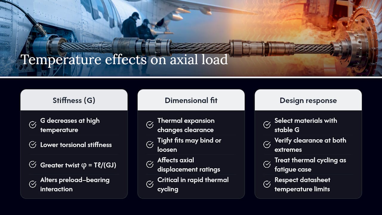
How Do Temperature Changes Affect Axial Load Handling in a Flexwelle?
Temperature swings change two things simultaneously: material stiffness and dimensional fit, both of which alter how a flexwelle handles axial load. Shear modulus G is temperature-dependent, and a shaft core running near a material’s upper temperature limit will exhibit measurably lower torsional stiffness than the same shaft at room temperature. That shift changes the angle of twist under a given torque, per φ = Tℓ/(GJ), and can also change how axial preload interacts with bearing clearance.
Thermal expansion of shaft casings, couplings, and end fittings introduces a second effect. Components sized for a tight fit at ambient temperature can bind or loosen across an operating temperature range, which directly changes the axial clearance available at the shaft ends. In confined aerospace installations, where thermal cycling can be rapid and repeated, this clearance shift matters more than in a steady-state industrial environment.
Composite and elastomeric flex-drive elements illustrate the trade-off clearly. Product families like the Vulkan N-Flex drive shaft combine torsional elasticity with displacement capability, but datasheets for these components specify numeric temperature ranges precisely because axial displacement ratings are not constant across the operating envelope. A shaft rated for a given axial displacement at 20°C may not hold that rating at 80°C.
Practical design response includes selecting core and sheath materials with stable shear modulus across the expected temperature range, verifying axial clearance at both temperature extremes rather than only at ambient, and treating thermal cycling as a fatigue-relevant load case rather than a static one.
Balancing Packaging Freedom Against Axial-Load Robustness
Flexible shafts earn their place in a design because they solve a packaging problem: routing torque through a confined or misaligned path that a rigid shaft cannot navigate. That freedom is never free. Every degree of torsional compliance you accept in exchange for routing flexibility is a degree of positional uncertainty you must account for somewhere else in the control loop, and every axial degree of freedom you build in to accommodate thermal growth is an axial load path you have to verify against a bearing or coupling rating.
The mistake engineers make most often is treating axial force as a secondary check performed after torque sizing is finished. Axial reactions from helical gearing or angled installation can exceed a motor’s rated axial limit even when torque sizing looks conservative. When axial loads are borderline against a datasheet limit, build a prototype and instrument it. Calculated reaction forces and measured ones diverge often enough that the extra step is worth the schedule cost. If your application sits near these boundaries, contact a flexible shaft supplier with the checklist items outlined above.
— Uli
Get Engineering Support for Custom Flexible Shaft Configurations
Some suppliers design both standard and custom flexible shafts, and engineering support for such catalogs can resolve axial-load questions before a shaft is cut. Where a generic supplier hands you a spec sheet and leaves axial reaction calculations to the user, engineering teams at experienced suppliers may work through torque, RPM, coupling interface, and axial load requirements directly with your design team before quoting a configuration.
When reaching out, include operating torque, RPM range, peak and typical axial loads, mounting geometry, and target service life in cycles. That information lets an engineer size the core, sheath, and end fittings against your actual duty cycle rather than a generic rating. Review the flexible shaft applications page for application-specific guidance, or go directly to the custom flexible shaft design page to start a configuration inquiry with your torque and axial load parameters in hand.
Sources
- MIT Unified Engineering — torsion chapter (lecture notes)
- MathWorks — Flexible Shaft block documentation
- Siemens SIMOTICS 1FT2 project manual — radial and axial forces
FAQ
What Causes Axial Forces in a Flexible Shaft?
Axial forces most commonly arise from helical gear meshes, angled installation geometry, and end-thrust reactions from driven tooling pressing back along the shaft’s rotational axis.
How Do You Calculate the Angle of Twist in a Flexwelle?
Use φ = Tℓ/(GJ), where T is applied torque, ℓ is shaft length, G is the material’s shear modulus, and J is the polar moment of inertia for the cross-section.
When Should You Use FEA Instead of Hand Calculations?
Escalate to FEA or multi-body simulation when torsion, axial load, and bending act together, when the cross-section is non-circular or warping-prone, or when dynamic coupling between shaft compliance and a control loop needs modeling.
Why Do Motor Datasheets List Axial Force Limits?
Motor and gearbox datasheets specify allowable axial forces because exceeding them, for example by mounting a direct helical-gear pinion, can overload the motor’s internal bearings and shorten service life.
Can Biax-flexwellen Help Size a Shaft for Axial Load Requirements?
Yes. Biax-flexwellen provides engineering support for both standard and custom flexible shaft configurations, working from torque, RPM, axial load, and mounting geometry data supplied by the design engineer.
Recommended
- Shaft Design Checklist for Mechanical Engineers
- 7 Expert Flexible Shaft Maintenance Tips for Engineers
- Torque Transmission Best Practices for Flexible Shafts
- Custom Flexible Shaft Configuration Guide for Engineers
Related Topics
Send your spec inquiry
Custom flexible shafts for your application — we quote within 1 working day.