The Role of Shaft Couplings in Power Transmission
22 May 2026TL;DR:
- Shaft couplings do more than connect shafts; they transmit torque, manage misalignment, and damp vibrations in machinery. Proper selection and maintenance—considering factors like torsional stiffness and misalignment tolerance—are essential for reliable long-term operation. In aerospace and industrial systems, flexible shaft couplings accommodate spatial constraints and prevent premature wear caused by misalignment and overloads.
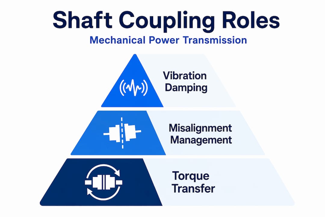
Shaft couplings are frequently reduced to a single function in engineering conversations: connecting two shafts. That framing understates what these components actually do. The role of shaft couplings in modern power transmission systems extends to torque management, misalignment compensation, vibration isolation, and protecting downstream equipment from overload events. In aerospace actuation systems and industrial finishing machinery alike, the coupling is often the element that determines whether a drivetrain performs reliably over thousands of operating hours or degrades prematurely. This article addresses the mechanical principles, design tradeoffs, and selection criteria that engineers need to apply these components effectively.
Table of Contents
- Key takeaways
- The role of shaft couplings in mechanical systems
- Mechanical design considerations for coupling selection
- Managing misalignment: effects, tolerances, and best practices
- Shaft coupling types and aerospace-relevant designs
- My perspective on what engineers consistently get wrong
- Flexible shaft solutions from Biax-flexwellen
- FAQ
Key takeaways
| Point | Details |
|---|---|
| Beyond simple connection | Shaft couplings transmit torque, manage misalignment, and protect machinery from shock and overload. |
| Oversizing improves fatigue life | Select couplings at 20 to 30% above average service torque to extend elastic element life under dynamic loads. |
| Misalignment has measurable consequences | A 2-mil offset misalignment can reduce bearing life by 50%, making precision alignment non-negotiable. |
| Torsional stiffness affects accuracy | In servo and CNC drives, insufficient torsional stiffness causes lost motion and positioning error. |
| Flexible does not mean forgiving | Operating at maximum rated misalignment accelerates wear by 3 to 10 times, requiring proper cold alignment regardless of coupling type. |
The role of shaft couplings in mechanical systems
The function of shaft couplings goes well beyond mechanical linkage. Each coupling in a drivetrain performs several simultaneous roles, and a failure to account for any one of them during selection leads to accelerated wear, vibration problems, or catastrophic component failure.
The primary role is torque transmission. A coupling must transfer rotational force from a driving shaft to a driven shaft without slipping, binding, or introducing torsional backlash that degrades system response. For servo-driven systems, this requirement alone shapes the entire coupling specification.
Beyond torque, shaft couplings in machinery must manage three distinct forms of shaft misalignment:
- Angular misalignment: The shaft centerlines intersect at an angle rather than running parallel. This produces axial vibration, typically appearing at 1x and 2x running speed in vibration frequency spectra.
- Parallel (offset) misalignment: The shafts run parallel but are laterally offset. This generates radial vibration at 2x RPM, which loads bearings cyclically and accelerates seal wear.
- Axial misalignment: Shafts are displaced along their common axis, introducing compressive or tensile forces that coupling designs must absorb without transmitting them to connected equipment.
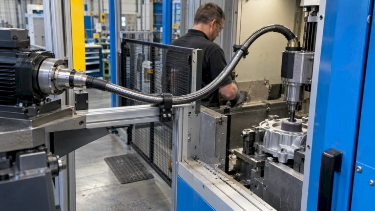
Vibration damping is the third major function. Elastomeric and flexible-element couplings attenuate torsional shock loads and high-frequency vibration before they reach gearboxes, encoders, or precision spindles. This is particularly important in applications such as deburring spindles and grinding drives where cutting forces are intermittent and variable.
Properly selected flexible couplings also act as fail-safes. When a drivetrain encounters an overload event, the coupling’s elastic element is designed to fail before the motor or gearbox, limiting damage to the least expensive and most replaceable component in the assembly.
Mechanical design considerations for coupling selection
Selecting the right coupling requires evaluating several interdependent design parameters. Getting this wrong creates problems that are difficult to diagnose once a machine is commissioned.
Torsional stiffness and positioning accuracy
Torsional stiffness is the coupling’s resistance to angular deflection under applied torque. In positioning-critical applications such as CNC machining centers, servo actuators, or flap actuation shafts in aerospace, low torsional stiffness introduces lost motion. The driven shaft lags behind the commanded position, and the control system either compensates with increased gain (risking instability) or accepts the positioning error.
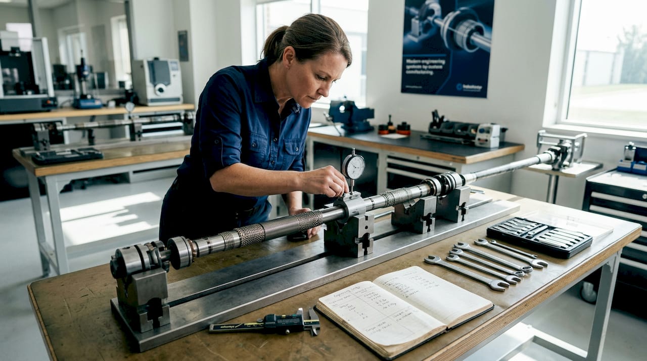
Engineers working on precision drives should treat torsional stiffness as a primary selection criterion, not an afterthought. The tradeoff is real: higher stiffness typically means reduced misalignment tolerance and increased bearing loads from shaft offsets. Finding the correct balance requires knowing the application’s positional accuracy requirements and the expected misalignment budget.
Fatigue life and oversizing guidelines
Couplings operating under dynamic loads experience cyclic stress on their elastic elements with every torque reversal. The recommendation from coupling engineering practice is to oversize by 20 to 30% above the average service torque. This margin accounts for peak loads during startup, direction reversals, and inertia-driven spikes that exceed steady-state values.
Material selection for elastic elements matters equally. Polyurethane and high-grade rubber compounds with high reverse-bending fatigue resistance maintain their mechanical properties over a longer service life than standard compounds, especially in applications with frequent direction changes.
Pro Tip: When calculating service torque for coupling selection, multiply the nominal torque by the application service factor before comparing against coupling ratings. For shock-loaded drives such as deburring or grinding spindles, use a service factor of 1.5 to 2.0.
Design constraints in confined spaces
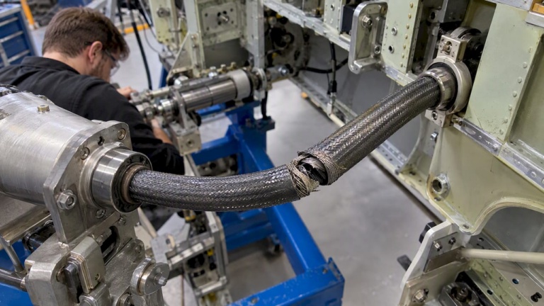
Aerospace and industrial machinery installations frequently impose geometric constraints that limit coupling selection to designs with short overall length and small outer diameter. Flexible shaft assemblies are often the only viable solution in confined routing environments, such as valve override systems or thrust reverser actuation, where a solid shaft and rigid coupling assembly cannot physically fit the installation path.
Managing misalignment: effects, tolerances, and best practices
Misalignment is one of the leading causes of premature bearing failure in rotating machinery, accounting for a significant share of unplanned shutdowns across industrial sectors. Understanding what each misalignment type does to a machine is prerequisite knowledge for any engineer specifying couplings or planning maintenance intervals.
Effects on machine health
The dynamic forces generated by misalignment scale with the square of machine speed. At high RPMs, even small angular or offset deviations generate bearing loads that far exceed design limits. A 2-mil offset misalignment alone can cut bearing service life by 50%. Seal leaks, accelerated coupling element wear, and shaft fatigue follow closely.
Vibration signature analysis allows maintenance engineers to distinguish between misalignment types. Angular misalignment produces dominant axial vibration at running speed. Offset misalignment produces strong radial vibration at twice running speed. These patterns support targeted diagnosis rather than broad-spectrum replacement.
Alignment correction procedure
Proper alignment of shaft couplings in machinery requires a structured sequence:
- Pre-alignment checks: Inspect soft foot conditions, check baseplate integrity, and verify that hold-down bolts are correctly torqued before taking any measurements.
- Rough alignment: Use straightedge and feeler gauge methods to bring shafts into approximate alignment before switching to precision instruments.
- Precision measurement: Deploy laser alignment systems to capture accurate offset and angular deviation readings across all measurement planes.
- Thermal growth compensation: Calculate expected thermal expansion of machine casings at operating temperature. Steel expands approximately 0.006 inches per foot per 100°F. Offset cold alignment to compensate so that the system runs aligned at temperature.
- Verification: Take a final set of laser measurements after securing all fasteners and recheck at operating temperature if conditions allow.
Alignment tolerance by coupling type
| Coupling type | Offset tolerance (typical) | Angular tolerance (typical) | Notes |
|---|---|---|---|
| Rigid coupling | 0.001 in or less | Near zero | Requires near-perfect alignment; no error absorption |
| Jaw/elastomeric | 0.005 to 0.015 in | Up to 1.0° | General industrial use; moderate misalignment capability |
| Disc/membrane | 0.002 to 0.005 in | Up to 0.5° | High torsional stiffness; preferred for servo drives |
| Flexible shaft | Application-dependent | High angular range | Suited for confined geometry and non-linear routing |
Operating a flexible coupling continuously at its rated misalignment limit accelerates wear by 3 to 10 times compared to well-aligned operation. The rated misalignment capacity of a coupling is not a target. It is a damage threshold. Engineers should target operation within 10 to 25% of the rated capacity to preserve service life.
Shaft coupling types and aerospace-relevant designs
Understanding shaft coupling types and their mechanical behavior is necessary for matching coupling performance to application demands. The classification by rigidity defines most of the relevant tradeoffs.
Rigid couplings transmit torque without any flexibility. They require precise shaft alignment and offer no vibration isolation or misalignment compensation. Their primary advantage is zero backlash and full torsional stiffness, making them suitable for applications where alignment is controlled with high precision and dynamic accuracy is critical.
Flexible couplings incorporate an elastic element, a disc, a membrane, or a compliant jaw insert, that absorbs misalignment and attenuates vibration. The selection of shaft coupling type depends on the specific combination of torsional stiffness, misalignment tolerance, and fatigue life required by the application.
Key flexible coupling types for industrial and aerospace applications:
- Jaw couplings: Low cost, moderate torsional stiffness, good shock absorption. Used in general industrial drives, pumps, and fan applications.
- Disc and bellows couplings: High torsional stiffness with controlled misalignment capacity. Preferred in servo drives, CNC axes, and precision actuators.
- Hydrodynamic couplings: Transmit torque through fluid shear, providing speed isolation and soft start characteristics. Found in heavy industrial drives and some aerospace auxiliary power systems.
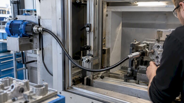
- Flexible shafts: Transmit torque through a helically wound core inside a protective sheath, permitting non-linear routing and high angular deviation. Used extensively in aerospace valve overrides, thrust reverser controls, and finishing equipment in confined installations.
For aerospace actuation systems, the functional requirements are particularly demanding. Flap and slat actuation shafts must maintain positional accuracy under thermal cycling while routing through constrained aircraft structure. Flexible shaft assemblies with precision coupling interfaces satisfy this requirement where rigid configurations cannot physically fit. The ability to route around structural members, combined with reliable torque transmission, makes flexible shaft designs a practical solution for synchronization shafts and valve override systems where installation geometry is non-negotiable.
My perspective on what engineers consistently get wrong
I’ve reviewed coupling selections across dozens of industrial and aerospace machine builds, and one pattern appears repeatedly. Engineers treat the flexible coupling’s rated misalignment as permission to skip precise alignment during installation. It is not.
In my experience, the most damaging installations are not the ones with clearly wrong couplings. They are the ones where a competent engineer selected a technically adequate flexible coupling and then relied on it to absorb an alignment deficit that should have been corrected mechanically. The coupling performs the task, but it performs it at a cost: accelerated elastic element wear, increased bearing loads, and vibration that propagates into precision components.
What I’ve found to matter most in long-service installations is treating alignment as a recurring maintenance task, not a one-time commissioning step. Thermal growth shifts alignment at every startup cycle. Machine bases settle. Soft foot conditions develop over time. The coupling absorbs these changes quietly until it doesn’t.
For engineers working on servo-driven or precision positioning systems, torsional stiffness deserves the same attention as misalignment tolerance. Lost motion from compliant couplings degrades loop gain performance in ways that are often misattributed to control tuning rather than mechanical compliance. Addressing the coupling first frequently resolves the control problem without any software change.
The long-term reliability of a drivetrain depends on treating the coupling not as a fixed component, but as a wear element that requires monitoring and periodic replacement on a defined schedule.
— Uli
Flexible shaft solutions from Biax-flexwellen
The technical requirements described in this article, torque transmission in confined geometries, precision coupling interfaces, and fatigue-resistant flexible elements, are the design constraints that Biax-flexwellen addresses in its product development for industrial and aerospace customers.
Biax-flexwellen (Schmid & Wezel GmbH) designs and manufactures industrial flexible shaft solutions for finishing, machining, and actuation applications where solid shaft assemblies are not viable. Products are configured to customer torque and RPM specifications, with coupling interface options matched to the driven equipment. Standard and custom protective sheath configurations are available for routing in tight installation envelopes.
Machine builders and system integrators working on deburring, grinding, polishing, or aerospace actuation applications can contact Biax-flexwellen directly to discuss technical requirements. Engineering guidance on shaft design for precision applications is available through the website.
FAQ
What is a shaft coupling and what does it do?
A shaft coupling is a mechanical component that connects two rotating shafts to transmit torque while accommodating misalignment, absorbing vibration, and protecting equipment from overload. Its function extends beyond simple connection to active management of dynamic forces in the drivetrain.
How does misalignment affect coupling and bearing life?
Even a 2-mil offset misalignment can reduce bearing service life by 50%. Operating a flexible coupling at its maximum rated misalignment accelerates wear on the elastic element by 3 to 10 times compared to properly aligned operation.
When should engineers choose a flexible coupling over a rigid one?
Flexible couplings are appropriate when some degree of shaft misalignment is unavoidable, vibration isolation is required, or the installation geometry prevents perfect alignment. Rigid couplings are preferred when positional accuracy and zero backlash are critical and alignment can be controlled precisely.
Why does torsional stiffness matter in coupling selection?
Low torsional stiffness in a coupling causes the driven shaft to lag behind the commanded position under load, introducing positioning error. This is particularly relevant in CNC machines, servo axes, and aerospace actuation systems where angular accuracy is a system performance requirement.
How often should shaft couplings be inspected and replaced?
Inspection intervals depend on operating conditions, but flexible coupling elements should be checked at every planned maintenance shutdown for wear, cracking, or permanent deformation. Thermal growth, base settlement, and load changes shift alignment over time, making periodic realignment and element replacement part of a reliable maintenance program.
Recommended
- Flexible shaft applications for industrial manufacturing
- Flexible Shaft Drive Solutions: Unlocking Compact Efficiency
- Shaft flexibility: the key to optimized industrial drives
- 7 Practical Examples of Shaft Drive Solutions for Engineers
Related Topics
Send your spec inquiry
Custom flexible shafts for your application — we quote within 1 working day.