
Optimize industrial torque transmission workflow: 5 key steps
21 April 2026TL;DR:
- Proper load definition and stress analysis prevent early torque transmission failures.
- Flexible shafts and harmonic drives enable reliable, space-efficient torque transfer in tight applications.
- Fatigue from cyclic loads at stress concentrations is the main failure risk, not static overloads.
Torque transmission failures in compact finishing applications are rarely random. They follow predictable patterns rooted in overlooked design decisions made long before the first part runs. In industrial deburring, grinding, and polishing cells, even minor misalignments or undersized shafts can cascade into costly downtime, scrapped components, and full redesign cycles. The good news is that a structured, stepwise workflow eliminates most of these risks before they materialize. This guide walks through five critical stages, from load definition to troubleshooting, so engineering teams can build reliable, high-efficiency torque transmission systems for even the most space-constrained and complex manufacturing environments.
Table of Contents
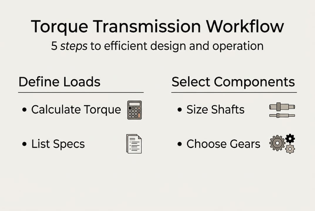
- Define loads and set requirements
- Choose and size transmission elements
- Integrate compact transmission solutions
- Verify, optimize, and troubleshoot your workflow
- Our perspective: Where engineers win (and lose) with torque transmission
- Discover flexible torque transmission solutions for your workflow
- Frequently asked questions
Key Takeaways
| Point | Details |
|---|---|
| Accurate load definition | Correctly calculating torque and loads prevents workflow failures and oversized components. |
| Proper sizing methodology | Using industry-standard shaft sizing ensures compactness and long life in tight applications. |
| Integration with modern drives | Flexible and harmonic drives deliver space-saving reliability for complex industrial finishing. |
| Thorough verification | Simulation and testing are crucial to catching fatigue and misalignment risks before failure. |
| Continuous optimization | Document lessons learned and update your workflow with real-life test data for robust designs. |
Define loads and set requirements
Every reliable torque transmission design starts with a complete picture of the system’s loading conditions. Skipping or shortcutting this stage is the most common reason that otherwise well-engineered assemblies fail prematurely in service.
Begin by compiling all system requirements into a single reference document. This should capture nominal torque, peak torque, rotational speed, input power, bending forces, axial loads, and support boundary conditions. Knowing where and how the shaft is constrained matters as much as knowing the loads themselves.
The standard formula for torque calculation is T = (P × 60) / (2πN), where T is torque in newton-meters, P is power in watts, and N is rotational speed in revolutions per minute. This gives you the nominal operating torque. From there, you must apply load factors for dynamic and shock conditions, which will be covered in the next section.
Use shaft design calculations early in the process to validate your assumptions against real application constraints before committing to any geometry.
Required parameters and example reference values:
| Parameter | Unit | Typical range | Notes |
|---|---|---|---|
| Nominal torque | Nm | 5 to 500 | Application-dependent |
| Peak/shock torque | Nm | 1.5 to 3× nominal | Apply shock factor |
| Rotational speed | rpm | 500 to 20,000 | Depends on process |
| Input power | W | 50 to 5,000 | Motor output |
| Shaft bending load | N | Varies | Include tooling weight |
| Fatigue limit | MPa | 200 to 600 | Material-specific |
| Safety factor | — | 1.5 to 3.0 | Higher for shock loads |
Benchmark your requirements against load types: distinguish static loads from cyclic dynamic loads, and identify whether shock events are possible. For finishing applications involving intermittent tool contact, shock loads are almost always present.
A custom shaft configuration approach becomes necessary when standard components cannot meet combined torque, speed, and spatial constraints simultaneously.
Pro Tip: Always model peak and shock load cases explicitly, not only nominal operating conditions. Systems sized only for average loads will experience accelerated fatigue at stress concentration points during every transient event.
Document your load cases in numbered priority order:
- Steady-state nominal torque at rated speed
- Peak torque during tool engagement or startup
- Shock torque from unexpected tool contact or jamming
- Combined bending and torsional loads at critical cross-sections
- Thermal effects on material strength at operating temperature
Choose and size transmission elements
Once requirements are fully defined, selecting and sizing the right transmission hardware becomes a systematic exercise rather than a guessing process.

For shaft sizing, the ASME elliptic criterion combines bending and torsional stresses with shock and fatigue factors to determine the minimum required shaft diameter. The relevant factors include the combined loading coefficient, material endurance limit, surface finish correction, and stress concentration factors at keyways or shoulders. Keyways, in particular, introduce local stress concentrations that reduce effective fatigue strength by 25 to 40 percent compared to a smooth shaft of the same diameter.
For drive technology selection, use this comparison to narrow options quickly:
| Technology | Size envelope | Efficiency | Max continuous torque | Backlash |
|---|---|---|---|---|
| Solid shaft | Medium | Very high | Application-limited | Zero |
| Flexible shaft | Very compact | High | Up to ~150 Nm | Near-zero |
| Harmonic drive | Compact | High (up to 90%) | 172 Nm continuous | Near-zero |
| Planetary gearbox | Medium | High (up to 97%) | 5,500 Nm | Low |
| Belt drive | Large | Moderate | Limited by belt rating | None |
For flexible shaft drive selection in finishing applications, the decisive factors are available installation space, required bend radius, and whether the tooling side needs to rotate freely relative to the drive side.
Sizing procedure for shaft diameter:
- Calculate nominal torque using T = (P × 60) / (2πN)
- Apply shock factor (typically 1.5 to 2.5 for intermittent tool contact)
- Add bending moment contribution at the critical cross-section
- Apply ASME combined stress formula with selected safety factor
- Check against material yield and endurance limits
- Verify critical speed is at least 20 percent above maximum operating speed
For flexible shafts in automation, derating for bend radius is essential. A flexible shaft operating near its minimum bend radius requires a torque derating of up to 30 percent from its straight-line rating.
Pro Tip: In space-limited machining cells, harmonic drives deliver high torque density with near-zero backlash. They are the preferred choice when positional accuracy matters alongside torque transmission in a compact envelope.
Integrate compact transmission solutions
Sizing leads directly into solution integration, especially for advanced compact and high-precision applications. Getting integration right avoids the most common assembly-stage failures.
Switching from conventional rigid shaft arrangements to compact drives offers measurable design advantages:
- Reduced installation envelope by 40 to 60 percent in many finishing cell layouts
- Simpler routing around obstacles without universal joints or intermediate bearings
- Lower maintenance burden due to fewer wear interfaces
- Improved uptime from reduced alignment sensitivity
- Faster tooling changeover in multi-process stations
Critical speed is a key integration risk. To manage it, keep the shaft slenderness ratio (L/d, length divided by diameter) within acceptable limits for the operating speed range. Proper bearing placement reduces the effective unsupported length. For flexible shaft cores, the protective sheath acts as a distributed support, significantly raising the effective critical speed compared to an unsupported solid shaft.
Note on fatigue and stress concentrations: Fatigue, not static overload, is the dominant failure mode in compact torque transmission applications. Compact layouts concentrate stress at transitions, keyways, and bore interfaces. Every geometric discontinuity is a potential fatigue initiation site. Design for fatigue life first, then verify static strength.
For shock load resilience, use compliant couplings or flexible shaft cores that absorb transient energy rather than transmitting it as peak stress into the driven assembly. This is particularly valuable in deburring and grinding applications where tool contact is unpredictable.
Use simulation tools to validate routing geometry, improving design efficiency before any physical prototype is built. Misalignment between input and output caused by thermal expansion or fixture variation is best identified and corrected in the digital model.
Pro Tip: Before cutting parts or ordering shafts, run a full misalignment sensitivity analysis in your simulation environment. Even a 1 to 2 degree angular offset can reduce flexible shaft service life significantly if the sheath support is not correctly positioned. For flex shafts in tight spaces, this step is not optional.
Verify, optimize, and troubleshoot your workflow
With the system integrated, verification is the stage that separates functional designs from production-grade ones. Skipping or compressing this phase is where many projects pay the price later.
Follow this verification sequence:
- Simulation review: Confirm torque capacity, critical speed margin, and misalignment tolerance with FEA or multibody dynamics tools. Simulation optimizes transmission sizing and identifies misalignment risks before physical hardware is committed.
- Static load test: Apply maximum expected torque and bending load and confirm no permanent deformation or coupling slip.
- Endurance test: Run the system through a representative duty cycle, including peak and shock events, for a defined number of cycles.
- Vibration and resonance check: Measure vibration signatures at all operating speeds to confirm no resonance within the working range.
- Thermal check: Monitor temperature rise at bearings, couplings, and shaft interfaces after full-load running.
Common issues that emerge during verification:
- Stress concentrations at keyways or shoulder fillets that were underestimated in the analytical model
- Dynamic loads in actual service that exceed the originally specified shock factor
- Insufficient redundancy in the drive path, leaving no fallback if a coupling fails
- Vibration modes that shift under load due to softening of compliant elements
For boosting shaft life in high-cycle applications, material selection and surface finish improvements at critical sections can extend service life significantly without dimensional changes.
Review flex shaft case studies from comparable finishing applications to benchmark your verification results against known service performance.
Pro Tip: Document all as-built dimensions, actual torque readings, and loading cycle counts from the verification phase. This baseline is indispensable for rapid troubleshooting and for justifying design changes in retrofit situations.
Our perspective: Where engineers win (and lose) with torque transmission
After working across many industrial finishing and machining applications, a consistent pattern emerges. The designs that fail are not usually the ones that got the nominal torque calculation wrong. They are the ones that underestimated cycle count, ignored fatigue accumulation at stress concentration points, or assumed that the nominal loading profile represented real operating conditions.
Fatigue is the mechanism responsible for the vast majority of shaft and coupling failures. Static overload events do occur, but they are recoverable if safety factors were applied. Fatigue is cumulative and silent. It progresses at stress levels well below yield, and by the time it is visible, the component is already compromised.
Keyways remain a necessary engineering compromise. They transmit torque reliably but introduce local stress concentrations that demand careful attention in precision shaft design. Alternatives like interference fits or spline interfaces reduce backlash but require tighter manufacturing tolerances and more disciplined assembly practices.
Simulation is valuable. But the most experienced engineers treat simulation results as the starting point for physical testing, not the conclusion. Real test data from the first prototype run almost always reveals load cases and vibration behaviors that the model did not predict. Design for the unexpected operating condition, not the idealized one.
Discover flexible torque transmission solutions for your workflow
BIAX Flexwellen engineers compact, high-performance flexible shaft and drive solutions purpose-built for demanding finishing and automation applications. Whether the challenge is transmitting torque around a corner, accessing a hard-to-reach deburring point, or maintaining precision in a multi-axis polishing cell, the BIAX product range covers standard and custom configurations. Explore proven flexible shaft manufacturing applications from real industrial environments, or start a direct consultation for your specific torque, speed, and spatial requirements. The BIAX engineering team supports custom flexible shaft design from initial specification through final validation, ensuring your system performs reliably from day one.
Frequently asked questions
How do I calculate torque requirements for my application?
Use the formula T = (P × 60) / (2πN), where P is power in watts and N is rotational speed in rpm. Always apply shock and dynamic load factors to the result before finalizing your shaft or drive selection.
What is the most common cause of torque transmission failure?
Fatigue from cyclic loading is the primary cause, not static overload. Stress concentrations at keyways, shoulders, and bore transitions are the typical initiation sites for fatigue cracks in finishing applications.
Why consider flexible shafts or harmonic gears in compact designs?
Harmonic gears and flexible shafts deliver high torque density in limited installation space, minimize backlash, and simplify routing compared to rigid shaft assemblies with intermediate bearings and universal joints.
How can simulation help optimize torque transmission?
Simulation tools predict misalignment risks and size transmission elements accurately before physical prototyping, reducing the cost and time of design iterations during verification.
Recommended
- Flexible Shafts in Automation: Precision in Tight Spaces – BIAX Flexwellen
- Flexible Shaft Drive Solutions: Unlocking Compact Efficiency
- Custom Flexible Shaft Configuration Guide for Engineers
- Flexible Shafts for Tight Spaces: Boosting Precision
- Smart cost-saving strategies for UK garages in 2026
Related Topics
Send your spec inquiry
Custom flexible shafts for your application — we quote within 1 working day.


