
Defining Rotational Power Transmission for Engineers
22 June 2026TL;DR:
- Rotational power transmission transfers torque and velocity from a prime mover to a load through components like shafts and gears. Selecting the right component type and gear ratio is essential for efficiency, high torque capacity, and reliable operation in industrial systems.
Rotational power transmission is the mechanical process of transferring torque and angular velocity from a prime mover to a driven load through components such as shafts, gears, belts, chains, and couplings. The industry term for this discipline is mechanical power transmission, and defining rotational power transmission within that context means specifying how torque, speed, and efficiency interact across every stage of a drivetrain. Industrial drivetrains transmit 100 kW to 5 MW at gear ratios from 1:1 to 100:1, covering everything from small CNC spindle drives to large conveyor systems. The three governing parameters are torque (T), rotational speed (N), and power (P), and every design decision in a drivetrain traces back to balancing these three values.
What is rotational power transmission and how does it work?
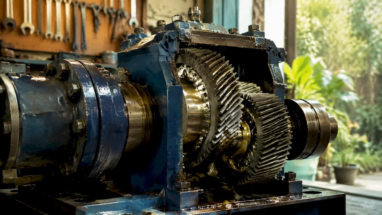
Mechanical power transmission converts the output of a prime mover, typically an electric motor or combustion engine, into usable motion at a driven shaft. Shafts transfer torque and motion, gears provide speed control and torque multiplication, belts handle misalignment and shock, and chains offer durability under high-cycle loading. Each component type serves a distinct function, and selecting the wrong one for a given load profile causes premature failure.
The relationship between torque, speed, and power is fixed by physics. Power equals torque multiplied by angular velocity. In imperial units, the working formula is P = (T × N) / 5252, where P is horsepower, T is torque in foot-pounds, and N is rotational speed in RPM. A 25 HP motor at 1,750 RPM produces 75 ft-lbs of torque. Doubling the speed at constant power halves the torque. This inverse relationship governs every gear ratio decision in a drivetrain.
Gear ratios determine how speed and torque are redistributed between input and output shafts. A ratio of 5:1 reduces output speed to one-fifth of input speed while multiplying output torque fivefold, minus losses. Efficiencies per stage typically range from 92% to 99%, depending on the transmission type. In a three-stage drivetrain, those losses compound, so selecting high-efficiency components at each stage is not optional for systems operating near their rated capacity.
Pro Tip: When specifying a drivetrain, calculate the total efficiency as the product of each stage’s efficiency. Three stages at 96% each yield a system efficiency of approximately 88.5%, not 96%.
How do different transmission types compare for industrial applications?
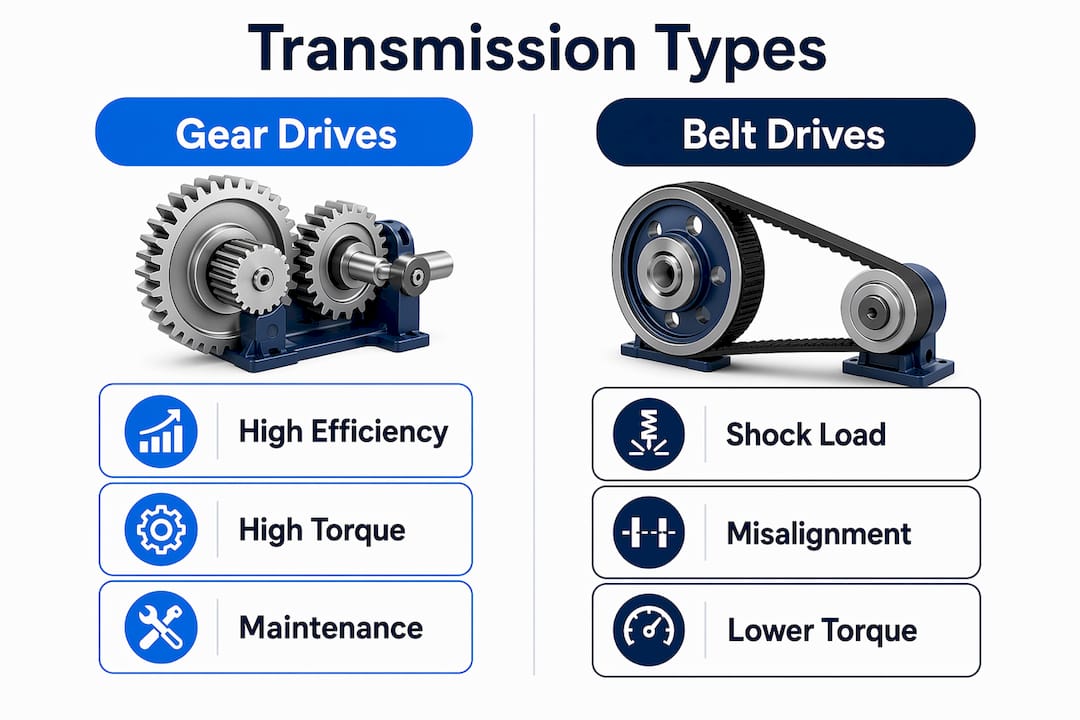
The three dominant mechanical transmission types are gear drives, belt drives, and chain drives. Each has a distinct efficiency profile, maintenance requirement, and torque capacity. The table below compares them across the criteria most relevant to machine design.
| Transmission type | Typical efficiency | Torque capacity | Maintenance | Best application |
|---|---|---|---|---|
| Helical gear drive | 97%–99% per stage | High | Low (sealed) | CNC machines, industrial gearboxes |
| Planetary gear drive | 95%–98% per stage | Very high | Low (sealed) | Heavy machinery, high-reduction drives |
| Worm gear drive | 50%–90% per stage | High | Moderate | Low-speed, high-ratio applications |
| V-belt drive | 93%–96% | Moderate | Moderate | HVAC fans, light conveyors |
| Roller chain drive | 97%–99% | High | High (lubrication) | Conveyor drives, agricultural machinery |
Helical gears produce less noise than spur gears because tooth engagement is gradual rather than instantaneous. Planetary gear systems stand apart from all other types because their coaxial input and output configuration enables load sharing across multiple planet gears. That load sharing is why planetary systems handle the highest torque densities in the smallest envelopes.
Single-stage planetary ratios run from 3:1 to 10:1; two-stage systems reach 10:1 to 50:1; three-stage configurations achieve up to 200:1. That range covers the majority of industrial reduction requirements without resorting to worm gears, which suffer significant sliding friction losses at high ratios. For conveyor drives and heavy machinery requiring ratios above 50:1, multi-stage planetary gearboxes are the standard engineering choice.
Belt drives absorb shock loads that would damage gear teeth and accommodate minor shaft misalignment without coupling hardware. Their limitation is slip under sustained high torque, which makes them unsuitable for precision positioning applications. Chain drives eliminate slip but require regular lubrication and periodic re-tensioning, adding maintenance overhead that sealed gear drives avoid entirely.
Pro Tip: For applications requiring ratios above 50:1, specify a multi-stage planetary gearbox rather than a single-stage worm gear. Single-stage ratios beyond 50:1 become inefficient due to sliding friction, and the efficiency penalty compounds at high duty cycles.
How to calculate torque and speed in a rotational power system
Accurate torque and speed calculations prevent undersizing and eliminate unnecessary safety margins that add cost and weight. The fundamental formula is HP = (T × RPM) / 5252. Rearranged to solve for torque: T = (HP × 5252) / RPM. This gives the required output torque for any known power and speed combination.
The steps for a complete drivetrain calculation are:
- Define the load torque requirement. Calculate the torque the driven machine needs at its operating speed. Include peak torque from startup or shock loads, not just steady-state values.
- Select the target output speed. Determine the RPM the driven shaft must reach. This sets the required gear ratio when combined with the motor’s rated speed.
- Calculate the gear ratio. Divide motor speed by required output speed. A 1,750 RPM motor driving a shaft at 350 RPM needs a 5:1 ratio.
- Apply efficiency corrections. Divide the required output power by the total drivetrain efficiency to find the motor power needed at the input.
- Verify shaft fits and tolerances. For shafts running above 3,000 RPM, specify an H7/k6 interference fit between hub and shaft. Incorrect fits cause fretting corrosion and loss of torque transfer integrity.
The 5252 constant is not arbitrary. It derives from 33,000 ft-lb/min per horsepower divided by 2π radians per revolution. Engineers who treat it as a generic conversion factor make errors when working outside standard RPM ranges or when mixing SI and imperial units. Always confirm unit consistency before applying the formula.
Matching the prime mover’s operating characteristics to load requirements improves both efficiency and component life. A motor running at 80% of its rated load typically operates at peak efficiency. Oversizing a motor to add margin pushes it into a low-efficiency operating region and increases capital cost without improving reliability.
What design challenges arise in rotational power transmission systems?
Real drivetrains face constraints that theoretical calculations do not capture. Shaft misalignment, mechanical shock, thermal expansion, and space restrictions all affect component selection and system reliability.
Key design challenges engineers must address:
- Shaft misalignment. Angular and parallel misalignment between connected shafts generates bending loads that accelerate bearing wear. Couplings manage shaft misalignment and mechanical shock, protecting gears and bearings from forces outside their design envelope. Flexible couplings accommodate misalignment up to several degrees of angular offset and several millimeters of parallel offset, depending on type.
- Mechanical shock loads. Impact loads from machine startup, reversals, or process variations can exceed steady-state torque by a factor of two or more. Elastomeric couplings and belt drives absorb these peaks. Rigid couplings transmit them directly to gears and shafts.
- High reduction ratios in confined spaces. Single-stage transmissions cannot achieve ratios above 10:1 without compromising efficiency or increasing envelope size. Multi-stage configurations solve this but require careful alignment of intermediate shafts.
- Lubrication and thermal management. Gear mesh efficiency drops as operating temperature rises. Sealed gearboxes with synthetic lubricants maintain efficiency across wider temperature ranges than open-bath oil systems.
- Aerospace and confined-space applications. Thrust reverser actuation systems, flap and slat drives, and synchronization shafts in aircraft operate in confined envelopes with strict weight limits. These systems require shaft flexibility to accommodate offsets that rigid shafts cannot bridge without additional bearing supports.
Variable transmissions operate best within a ratio range of 0.7 to 1.3. Outside that range, contact stress rises sharply and durability drops. Engineers specifying variable-ratio systems must verify that the operating range stays within this band under all load conditions, including transient states.
Distinguishing fixed-ratio from variable-ratio transmission systems is a fundamental design decision. Variable systems require more complex load calculations and tighter manufacturing tolerances to maintain stable operation across their full ratio range.
Key Takeaways
Rotational power transmission requires precise matching of torque, speed, and component type at every stage to maintain efficiency and prevent premature failure.
| Point | Details |
|---|---|
| Core formula | Use HP = (T × RPM) / 5252 to calculate torque at any operating point. |
| Stage efficiency compounds | Multiply per-stage efficiencies to find total system efficiency across multi-stage drivetrains. |
| Planetary gears for high ratios | Specify multi-stage planetary gearboxes for ratios above 50:1 to avoid worm gear friction losses. |
| Shaft fit selection | Use H7/k6 interference fits on shafts above 3,000 RPM to prevent fretting corrosion. |
| Coupling selection matters | Match coupling type to misalignment and shock load conditions before finalizing shaft layout. |
What I have learned designing rotational power systems
The most common mistake I see in drivetrain design is treating the gear ratio as the primary design variable and working backward from there. The ratio is a result, not a starting point. The correct sequence is to define the load torque at the driven shaft, then select the motor operating point, and only then calculate the ratio that connects them.
Single-stage thinking is the second failure mode. Engineers reach for a single high-ratio worm gear because it simplifies the bill of materials. The efficiency penalty at ratios above 30:1 is real and measurable, and it compounds over the machine’s service life. A two-stage planetary solution costs more upfront and pays back through lower energy consumption and longer component life.
Tolerance selection for high-speed shafts is the detail that separates reliable drivetrains from ones that fail at 18 months. The H7/k6 fit specification exists for a reason. Fretting corrosion on a loose hub-to-shaft interface is a slow failure mode that does not show up in acceptance testing but destroys torque transfer integrity in service. Specify the fit correctly at the design stage. Retrofitting it after a field failure is expensive.
My practical recommendation: address misalignment and shock load requirements before finalizing shaft layout. Adding a flexible coupling or a shaft coupling for misalignment late in the design process forces compromises in envelope and bearing selection. Build the accommodation into the architecture from the start.
— Uli
Biax-flexwellen flexible shaft solutions for industrial drives
Biax-flexwellen designs and manufactures flexible shafts and drive solutions for industrial applications where rigid shaft layouts are not feasible. Their products transmit torque reliably in confined spaces, around obstacles, and across angular offsets that fixed shafts cannot accommodate. Flexible shafts from Biax-flexwellen are used in deburring, grinding, polishing, and finishing processes where the drive source and the tool head cannot share a common axis. The product range covers standard configurations and custom designs specified by torque, RPM, coupling interface, and shaft geometry. Engineers working on compact drive layouts can review flexible shaft applications for manufacturing or contact Biax-flexwellen directly for application-specific engineering guidance.
FAQ
What is rotational power transmission?
Rotational power transmission is the mechanical transfer of torque and angular velocity from a prime mover to a driven load using components such as shafts, gears, belts, chains, and couplings. Industrial systems operate across power ranges from 100 kW to 5 MW.
How is torque calculated in a rotational power system?
Torque is calculated using T = (HP × 5252) / RPM in imperial units. The constant 5252 derives from the unit conversion between horsepower and foot-pounds per minute.
What transmission type is best for high reduction ratios?
Multi-stage planetary gearboxes are the standard choice for ratios above 50:1. Single-stage worm gears become inefficient at high ratios due to sliding friction losses.
Why does shaft fit matter in high-speed drivetrains?
An H7/k6 interference fit between hub and shaft prevents fretting corrosion on shafts running above 3,000 RPM. Incorrect fits cause progressive torque loss and eventual drivetrain failure.
What is the difference between fixed-ratio and variable-ratio transmission?
Fixed-ratio transmissions maintain a constant speed and torque relationship between input and output. Variable-ratio systems adjust the ratio dynamically but operate reliably only within a ratio range of 0.7 to 1.3 before contact stress becomes damaging.
Recommended
- Optimizing Torque Transmission Methods for Engineers
- Optimize industrial torque transmission workflow: 5 key steps
- The Role of Shaft Couplings in Power Transmission
- Torque Requirements Workflow for Machinery Engineers
Related Topics
Send your spec inquiry
Custom flexible shafts for your application — we quote within 1 working day.


