Shaft flexibility: the key to optimized industrial drives
1 May 2026TL;DR:
- Correctly specifying shaft flexibility reduces stress, wear, and premature failures in rotating machinery.
- Flexibility influences critical speeds and vibrations, requiring careful modeling and design optimization.
- Oversimplified assumptions about rigidity can lead to resonance crossings and system-level failures.
Premature machine failures often trace back not to material defects or manufacturing errors, but to an incorrect specification of shaft flexibility. Many design engineers instinctively treat flexibility as a liability, favoring rigid shafts to minimize deflection and maintain positional accuracy. That assumption costs time, money, and service life. Shaft flexibility actually prevents excessive stress on bearings, seals, and couplings by accommodating thermal growth, operational loads, and geometric misalignment changes that are present in virtually every real-world installation. This article presents the engineering rationale, quantitative benchmarks, and design methodologies that allow engineers to specify shaft flexibility with precision and confidence.
Table of Contents
- What is shaft flexibility and why does it matter?
- Impacts of shaft flexibility on critical speeds and vibration
- Consequences of improper shaft flexibility: risks and failure modes
- Modeling and optimizing shaft flexibility in design
- Why most engineers misjudge shaft flexibility (and how to get it right)
- Enhance your drive solutions with expert flexible shaft design
- Frequently asked questions
Key Takeaways
| Point | Details |
|---|---|
| Flexibility prevents premature failure | Shaft flexibility is essential to accommodate misalignments and protect core machine components. |
| Balance is critical | Both insufficient and excessive flexibility can result in costly system failures and reduced efficiency. |
| Dynamic modeling optimizes design | Modern tools allow engineers to fine-tune shaft behavior and maximize system reliability. |
| Expert insights reduce risk | Leveraging simulation and correct modeling frameworks cuts down on trial and error in engineering new solutions. |
What is shaft flexibility and why does it matter?
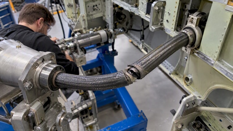
Shaft flexibility refers to the controlled capacity of a rotating shaft to deform under load without permanent deformation or loss of functional performance. Engineers typically distinguish three types of flexibility in rotating systems:
- Angular flexibility: the ability to accommodate angular misalignment between coupled components, such as between a motor output and gearbox input shaft
- Lateral flexibility: controlled radial deflection under transverse loads, relevant where bearing span, loading conditions, or mounting geometry vary during operation
- Torsional flexibility: the capacity to absorb torque spikes and oscillations before they propagate to connected components
These three modes are not independent. A change in shaft diameter, wall thickness, or material modulus affects all three simultaneously, which is precisely why rigid shafts create problems in dynamic environments. A rigid shaft transmits every load variation directly to adjacent components. Bearings absorb impact loads they were not designed for. Seals lose their contact geometry. Couplings experience edge loading.
Shaft flexibility is essential in rotating machinery to accommodate misalignment caused by thermal growth, operational loads, and machine flexing that occur continuously during service. This is not a marginal effect. Thermal expansion alone in a steel shaft running at elevated temperatures can shift shaft centerlines by several hundredths of a millimeter across moderate spans, well beyond the tolerance band of many precision bearings.
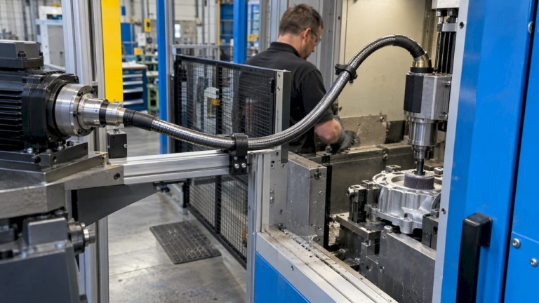
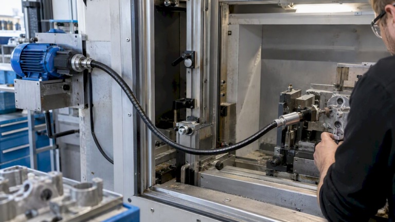
For industrial manufacturing applications such as deburring, grinding, and polishing, this matters directly. The tool-to-workpiece interface changes moment to moment. A shaft that cannot accommodate slight positional drift transfers that drift as load directly into the drive train.
| Shaft type | Flexibility level | Primary risk | Suitable for |
|---|---|---|---|
| Solid rigid shaft | Very low | Overloads bearings and seals | Fixed-geometry, precision positioning |
| Semi-flexible shaft | Moderate | Resonance if not modeled correctly | General industrial drives |
| Flexible shaft (wound core) | High | Excessive deflection if over-specified | Tight-space, high-misalignment environments |
| Hollow thin-walled shaft | Variable | Shear deformation, mode coupling | Weight-critical or high-speed rotors |
The practical consequence: specifying shaft flexibility is not a secondary task to be handled after the main drivetrain layout is complete. It should be integrated into the earliest design stages, alongside torque, speed, and environmental specifications.
Impacts of shaft flexibility on critical speeds and vibration
Every rotating shaft has critical speeds, rotational frequencies at which the excitation frequency coincides with a natural frequency of the shaft-rotor system, producing resonance. Operating at or near a critical speed generates destructive vibration amplitudes that accelerate wear across the entire drive train. Shaft flexibility directly determines where those critical speeds fall.
Higher shaft stiffness raises critical speeds, while greater flexibility lowers them and reduces vibration transmitted to support bearings. This creates a genuine engineering tradeoff. A stiffer shaft pushes critical speeds above the operating range, which sounds desirable, but it also transmits more load variation to bearings and mounts. A more flexible shaft absorbs vibration at supports but may introduce its own resonance risks if the critical speed drops into the operating range.
The following process reflects best practice for managing this tradeoff:
- Establish the operating speed range including startup and rundown transients, not just steady-state RPM
- Estimate initial critical speeds using analytical models (Rayleigh-Ritz or Timoshenko beam theory for preliminary assessment)
- Build a Campbell diagram plotting natural frequencies against operating speed to identify potential resonance crossings
- Use finite element analysis (FEA) to refine mode shapes and frequencies, especially for non-uniform geometry or flexible boundary conditions
- Verify mode separation ensuring a minimum margin (typically 15 to 20 percent) between any operating speed and the nearest critical speed
- Iterate shaft geometry adjusting diameter, wall thickness, or bearing span to relocate critical speeds while maintaining the required flexibility profile
Note: Gyroscopic effects in high-speed rotors add directional stiffness that shifts critical speeds differently in forward and backward whirl modes. For shafts operating above 10,000 RPM with significant rotor disk inertia, these effects must be included in the dynamic model. Ignoring them leads to non-conservative critical speed predictions.
The connection between torsional flexibility in drive solutions and vibration control is particularly relevant for applications that involve pulsed loads. Grinding spindles, for example, experience periodic cutting force variations. A shaft with appropriate torsional flexibility buffers those pulses before they reach the motor coupling, reducing high-cycle fatigue loading on both ends of the drive train.
| Design parameter | Effect on critical speed | Effect on vibration at supports |
|---|---|---|
| Increase shaft diameter | Raises critical speed | Increases transmitted force |
| Increase bearing span | Lowers critical speed | Reduces support reaction forces |
| Reduce shaft stiffness | Lowers critical speed | Reduces support vibration |
| Add intermediate bearing | Raises critical speed | Changes mode shapes |
Consequences of improper shaft flexibility: risks and failure modes
When shaft flexibility is incorrectly specified, either too high or too low, the failure sequence is well documented. The symptoms are predictable, but they are often misdiagnosed because they appear as bearing or seal failures rather than as a shaft specification problem.
Common failure modes from inadequate shaft flexibility include:
- Rapid bearing wear: excessive radial load variation causes non-uniform contact stress, reducing L10 bearing life by 40 to 60 percent in severe cases
- Seal leakage: shaft runout beyond the dynamic sealing range of lip seals or mechanical face seals causes intermittent contact loss, leading to lubricant loss and contamination ingress
- Fatigue cracking: cyclic bending stress concentrations at keyways, shoulders, or threaded sections initiate cracks that propagate to fracture under continued operation
- Coupling fretting and wear: angular and parallel misalignment transmitted through an overly rigid shaft loads gear or disc couplings outside their rated misalignment capacity
Excessive shaft deflection from insufficient stiffness creates bearing misalignment, seal leaks, fatigue cracking, and reduced L10 bearing life. The quantitative benchmark most relevant to sealing integrity is runout at the seal face. Keeping this value below 0.002 inches (0.05 mm) is a widely accepted threshold for standard industrial lip seals. Exceeding it consistently produces leakage and contamination that propagate through the lubrication system.

Pro Tip: Always measure dynamic runout at seal locations under representative operating loads, not just under static conditions. Thermal growth and bearing clearance changes can add 0.001 to 0.003 inches of additional runout that does not appear in cold, no-load measurements.
Applying custom design best practices from the outset reduces the likelihood of these failure modes reaching field conditions. Engaging flexibility specifications during conceptual design, rather than treating them as a retrofit corrective action, is what consistently extends shaft lifespan in demanding applications.
Key quantitative thresholds to track:
| Parameter | Acceptable limit | Consequence if exceeded |
|---|---|---|
| Runout at seal face | Less than 0.002 in. (0.05 mm) | Seal leakage, contamination |
| Total indicated runout (TIR) at coupling | Less than 0.003 in. (0.076 mm) | Coupling fatigue, vibration |
| Maximum lateral deflection | Less than L/1000 (beam span) | Bearing edge loading |
| Torsional wind-up angle | Application-specific | Positional error, backlash |
Modeling and optimizing shaft flexibility in design
Getting flexibility right in practice requires selecting the correct analytical model for the shaft geometry and operating conditions. Classical Euler-Bernoulli beam theory is adequate for long, slender shafts where the length-to-diameter ratio exceeds approximately 10. For shorter, thicker, or hollow shafts, shear deformation contributes significantly to total deflection, and Euler-Bernoulli predictions become non-conservative.

Designers use Timoshenko and HOSDT beam theories to model flexibility accurately for dynamic systems, especially with hollow or thin-walled shafts where shear effects are not negligible. The higher-order shear deformation theory (HOSDT) extends the Timoshenko approach by incorporating higher-order displacement field assumptions, improving accuracy for shafts where the length-to-diameter ratio is low.
A practical modeling workflow for R&D teams looks like this:
- Screen with classical beam theory to establish baseline stiffness and natural frequency estimates for initial geometry selection
- Apply Timoshenko beam model for hollow or moderately short shafts to capture shear deformation effects accurately
- Run FEA with 3D solid elements for complex geometries, variable cross-sections, or shafts with significant features such as keyways, splines, or bore profiles
- Generate Campbell diagrams from the FEA modal results to map all relevant natural frequencies against operating speed
- Verify mode separation margins and adjust geometry, material, or bearing placement to achieve required separation from critical speeds
- Validate predictions with physical runout measurements and vibration data from prototype testing before committing to production geometry
HOSDT models are superior for thick and short shafts, with errors below 5 percent compared to full 3D FEA, which makes them an efficient choice for iterative R&D optimization where full 3D simulation of each design variant is time prohibitive.
Pro Tip: For tight-space finishing design applications where shaft geometry is constrained by the working envelope, HOSDT models allow rapid iteration of wall thickness and bore diameter combinations without incurring the full computational cost of 3D FEA at each step. This directly accelerates development cycles.
The most common modeling mistake is underestimating shear effects in hollow shafts by defaulting to Euler-Bernoulli models. This produces an overestimate of shaft stiffness and an overestimate of critical speeds. The result is a design that appears safe on paper but experiences resonance crossings during operation. The configuration guide for engineers addresses this systematically, providing a structured process for matching modeling approach to shaft geometry from the earliest design phase.
Why most engineers misjudge shaft flexibility (and how to get it right)
The dominant instinct among mechanical engineers is that stiffer is safer. This comes from a reasonable place. A stiffer shaft deflects less under load, positions the rotor more precisely, and pushes critical speeds higher. In static or quasi-static applications, that logic holds. In dynamic, thermally variable, or geometrically constrained industrial environments, it creates more problems than it solves.
The persistent underestimation of flexibility’s positive effects comes from treating misalignment as a condition to be eliminated at installation rather than managed continuously during operation. Thermal cycles, transient load peaks, and gradual bearing wear all shift shaft centerlines during service life. A shaft specified at maximum stiffness with minimal flexibility cannot accommodate these shifts without transferring the resulting loads directly into adjacent components.
Optimal shaft design uses FEA and Campbell diagrams not just to verify that a design avoids resonance, but to actively position critical speeds and mode shapes to best advantage for the full operating envelope. This is a meaningful distinction. Using these tools for verification only, as many teams do, leaves significant performance margin on the table.
The practical lesson from years of applications in demanding drive environments is that simultaneous modeling of multiple flexible regions, including shaft cores, protective sheaths, coupling interfaces, and bearing mounts, consistently reveals interaction effects that single-component models miss. A shaft that meets its individual flexibility specification in isolation may still produce excessive system-level vibration because its flexibility couples unfavorably with a compliant bearing housing or a resonant machine frame.
Engineers who move beyond component-level thinking and model the full flexibility chain from motor output to tool interface produce designs that are both more reliable and more adaptable. For improving design efficiency in practical terms, this systems-level view of flexibility is the single most impactful shift available in the design process today.
Enhance your drive solutions with expert flexible shaft design
BIAX Flexwellen provides engineering support, standard components, and fully custom flexible shaft configurations for machine builders and industrial manufacturers working across finishing, machining, and automation applications. Whether the requirement involves a specific torque and RPM envelope, a constrained installation geometry, or a coupling interface that does not match standard catalog options, the technical team at BIAX Flexwellen works directly with design engineers to develop solutions that meet both performance and service life requirements. Explore how to improve machine design efficiency with flexible drive components, or contact us to discuss custom shaft design solutions tailored to your specific application parameters. Qualified technical inquiries receive direct engineering support.
Frequently asked questions
What is the primary reason for specifying shaft flexibility in industrial drives?
Shaft flexibility compensates for misalignments that occur during operation, reducing stress on bearings, seals, and couplings and minimizing premature component failures caused by misalignment-induced loading.
How does shaft flexibility affect vibration control in machinery?
Appropriately specified flexibility reduces vibration at supports and prevents resonance conditions by positioning critical speeds outside the operating range, lowering transmitted forces at bearing and mounting locations.
What is the risk of excessive shaft deflection?
Too much deflection causes bearing misalignment, seal leakage, fatigue cracking, and shorter system service life; maintaining runout below 0.002 inches at seal locations is a standard requirement for avoiding cascading failures.
Which modeling approaches are best for optimizing shaft flexibility?
For hollow or geometrically complex shafts, Timoshenko and HOSDT beam models provide high accuracy with manageable computational cost, making them the preferred choice for iterative R&D optimization where full 3D FEA at each design step is not practical.
Recommended
- Flexible shaft guide: Engineering compact drive solutions
- Flexible Shaft Drive Solutions: Unlocking Compact Efficiency
- Torsional flexibility for precision industrial drive solutions
- How flexible shafts improve machine design efficiency
Related Topics
Send your spec inquiry
Custom flexible shafts for your application — we quote within 1 working day.