Custom Shaft Configuration Advantages for Engineers
8 July 2026TL;DR:
- Custom shaft configurations are engineered for specific applications, offering better reliability in demanding environments. They optimize geometry, material, tolerances, and manufacturing methods to control vibration, improve fatigue life, and fit confined spaces. Proper early collaboration with suppliers ensures cost-effective, high-performance solutions tailored to operational needs.
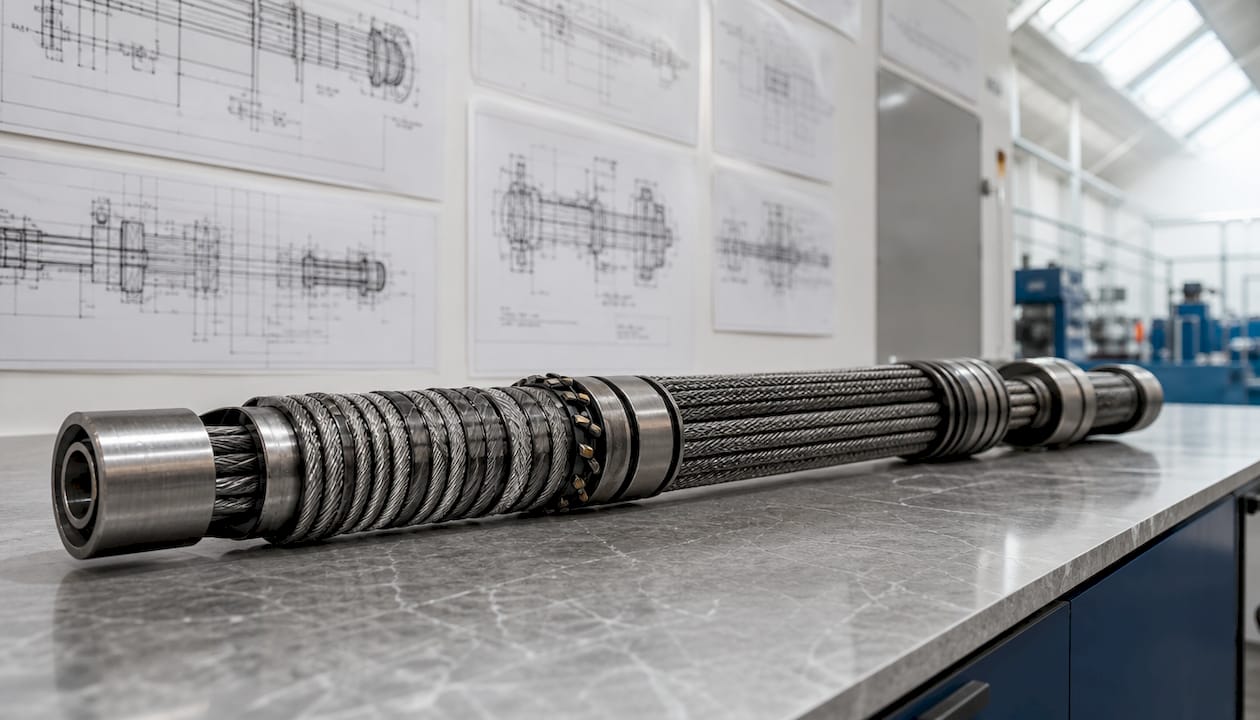
Custom shaft configurations are engineered adaptations of shaft geometry, material selection, tolerances, and manufacturing processes to meet the precise demands of a specific application. Standard off-the-shelf shafts cover common use cases, but they fail when operating conditions involve confined installation spaces, asymmetric loading, high rotational speeds, or corrosive environments. The advantages of custom shaft configurations become most apparent in demanding systems such as thrust reverser actuation, flap and slat drives, valve override mechanisms, and synchronization shafts, where a generic component simply cannot deliver the required reliability. Biax-flexwellen supports machine builders and industrial manufacturers through this engineering process, from function definition through to finished component.
1. Advantages of custom shaft configurations for vibration control
Vibration is the primary cause of premature bearing failure, seal degradation, and fatigue cracking in rotating shafts. Custom configurations address this directly by tailoring the shaft’s geometry and balancing grade to the specific operating speed range.
High-speed industrial drive systems require balancing grades such as G2.5 or G6.3 to manage vibration in slender shafts with length-to-diameter ratios exceeding 25:1. A shaft balanced to G2.5 carries a residual imbalance tolerance roughly half that of G6.3, which matters significantly at speeds above 3,000 RPM.
Straightness, runout, and concentricity all directly affect load distribution across bearing journals. A shaft with poor concentricity creates a rotating eccentric mass, which generates cyclic forces that accelerate bearing wear. In-process measurement of these parameters during CNC machining prevents excess scrap and catches deviations before they compound.
Critical speed is the rotational frequency at which a shaft resonates. Long shafts require increased diameter or tubular designs to raise stiffness and push the critical speed well above the operating range. Custom design allows engineers to set this margin deliberately rather than accepting whatever a standard shaft provides.
Pro Tip: When specifying a custom shaft for a high-speed application, request a Campbell diagram from your supplier. It maps critical speed against operating speed and makes resonance risks visible before manufacturing begins.
Key parameters to specify for vibration control:
- Balancing grade (G2.5 or G6.3 for high-speed applications)
- Maximum allowable runout at bearing journals
- Concentricity tolerance relative to the shaft centerline
- Target critical speed margin above maximum operating speed
2. Material and manufacturing method selection
The choice of material and manufacturing method determines a shaft’s fatigue life, torsional strength, and resistance to environmental degradation. Getting this wrong at the design stage is expensive to correct later.
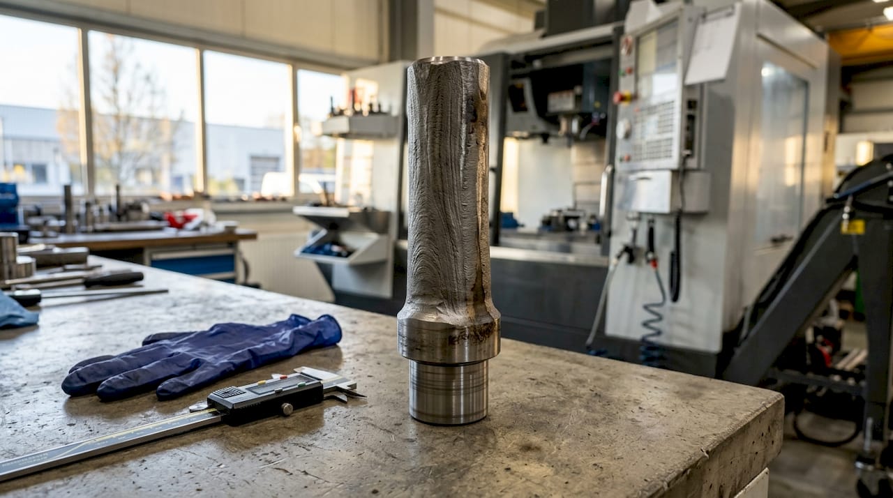
Common shaft materials each serve a distinct purpose. Alloy steels such as 4140 and 4340 offer high tensile strength and good machinability, making them the standard choice for high-torque industrial drives. Stainless steel grades suit corrosive or washdown environments. Aluminum reduces rotating mass in weight-sensitive aerospace applications. Carbon fiber composite shafts deliver the highest stiffness-to-weight ratio but require specialized joining and are not suited to high-temperature environments.
Custom forging aligns internal grain flow with the shaft geometry, producing significantly higher fatigue resistance and torsional strength compared to machined shafts. Forged shafts also tolerate impact loads better, which matters in systems subject to shock or sudden torque reversals.
Forging also enables near-net-shape geometry, which reduces the volume of material removed in downstream machining. That reduction translates directly into lower cycle time and material cost. Choosing between machining and forging depends on application load type, fatigue requirements, and geometric complexity.
Pro Tip: For shafts operating in corrosive environments, specify the exact chemical exposure to your supplier rather than simply requesting “corrosion-resistant material.” Chloride exposure, for example, rules out standard 304 stainless and points toward 316L or a duplex grade.
Material selection summary:
- 4140/4340 alloy steel: High torque, general industrial drives
- 316L stainless steel: Corrosive or washdown environments
- Aluminum alloys: Weight-sensitive aerospace and actuation systems
- Carbon fiber composite: Maximum stiffness-to-weight, low-temperature applications
- Forged vs. machined: Forging for fatigue-critical or impact-loaded applications; machining for geometric complexity and tight tolerances
3. Optimizing tolerances and surface finish
Tolerance specification is where engineers most commonly add unnecessary cost. Overly tight tolerances increase machining time and cost without improving shaft performance when the mating assembly does not require that level of precision. The correct approach is to specify tolerances based on the function of each shaft feature, not on a uniform high-precision standard applied across the entire part.
Bearing seats and gear fits require tight tolerances, typically ISO h6 or H7 fits, to control interference or clearance precisely. Seal running surfaces require specific surface finish values rather than tight dimensional tolerances. Non-functional surfaces, such as mid-span diameters with no mating component, need only enough precision to maintain balance and structural integrity.
Surface finish below Ra 0.4 μm is critical for sealing surfaces to prevent leaks. Bearing journals require Ra below 0.2 μm for smooth rotation and extended service life. These are not arbitrary numbers. A surface that is too rough creates micro-leakage paths past lip seals and accelerates abrasive wear on bearing raceways.
Cylindrical grinding and multi-process capability under one roof significantly improve precision and turnaround time for tight-tolerance custom shafts. Single-vendor processes reduce handoff errors and maintain consistent quality assurance across all features.
Tolerance and finish checklist:
- Specify ISO fit class (h6, H7, etc.) for each mating feature individually
- Define Ra values for sealing surfaces and bearing journals separately
- Leave non-functional surfaces at standard machining tolerances
- Require in-process measurement reports for critical dimensions
- Confirm supplier capability for cylindrical grinding if Ra below 0.4 μm is needed
4. Adaptability for aerospace and specialized industrial applications
Custom shaft configurations are the enabling technology for applications where standard components cannot meet installation or load requirements. Tailored shaft geometries and materials enable reliable function in confined, dynamic aerospace components such as thrust reverser actuation systems, flap and slat drives, and valve override mechanisms.
Thrust reverser actuation shafts must transmit high torque through a constrained envelope while tolerating vibration from engine operation and thermal cycling from proximity to exhaust gases. A standard shaft cannot satisfy all three constraints simultaneously. Custom stepped diameters allow the shaft to clear surrounding structure while maintaining adequate torsional stiffness at the loaded sections.
Synchronization shafts in flap and slat systems must maintain precise angular position across multiple drive stations. Any torsional compliance or backlash in the shaft introduces position error between surfaces, which creates asymmetric aerodynamic loading. Custom shaft design controls torsional stiffness and minimizes backlash through spline geometry and interference fit selection.
Features that custom configurations add for specialized applications:
- Stepped diameters to clear structural obstacles in confined envelopes
- Integral splines for direct gear or coupling engagement without additional hardware
- Asymmetric profiles to distribute load toward the stiffer end of a shaft
- Hollow bore designs to reduce weight or route hydraulic or electrical lines internally
- Surface treatments such as nitriding or hard chrome for wear resistance in dynamic environments
For engineers comparing shaft types for a given drive application, the rigid vs. flexible shaft selection guide from Biax-flexwellen provides a structured framework for that decision.
5. Cost-benefit planning for custom shaft projects
The financial case for a custom shaft configuration rests on total system cost, not component cost alone. A shaft that costs more to manufacture but eliminates a recurring maintenance interval or extends system life by a measurable margin delivers a clear return.
Defining the shaft’s function and operating environment before selecting materials or machining processes is the top priority for successful custom shaft manufacturing. Incomplete specifications lead to material mismatches and costly design revisions after tooling has been committed.
Early, clear communication with suppliers about operating speeds, torque, shock loads, and environmental conditions reduces manufacturing risk. Suppliers who receive complete functional data can flag over-specified features and suggest process alternatives that reduce lead time without compromising performance.
Budget-conscious specification practices:
- Define the operating environment fully before the first design review
- Apply tight tolerances only to functional surfaces with mating components
- Specify material grade based on actual thermal and chemical exposure, not conservatism
- Request design-for-manufacturability feedback from the supplier before finalizing drawings
- Evaluate total lifecycle cost, not just unit price, when comparing standard and custom options
Pro Tip: Ask your supplier to identify the three most cost-sensitive features on your shaft drawing. Relaxing tolerances or changing the process on even one of those features can reduce unit cost significantly without affecting function.
For a structured approach to shaft design decisions, the shaft design technical guide from Biax-flexwellen covers material selection, tolerance logic, and supplier collaboration in detail.
Key Takeaways
Custom shaft configurations deliver measurable performance, reliability, and cost advantages when geometry, material, tolerances, and manufacturing method are matched to the specific operating environment.
| Point | Details |
|---|---|
| Vibration control requires deliberate design | Specify balancing grade, runout limits, and critical speed margin for every high-speed shaft. |
| Material choice drives fatigue life | Forged alloy steel outperforms machined equivalents in torsional strength and impact tolerance. |
| Tolerances should match function, not convention | Apply ISO h6/H7 fits and Ra values only where mating assemblies require them to avoid excess cost. |
| Aerospace applications demand tailored geometry | Stepped diameters, splines, and hollow bores enable function in confined, high-load environments. |
| Early supplier communication reduces risk | Complete functional specifications before design review prevents material mismatches and costly revisions. |
Why I think most engineers specify custom shafts too late
Engineers typically bring custom shaft requirements to a supplier after the surrounding system design is already fixed. That sequence creates the most expensive kind of customization: geometry driven by spatial constraints rather than by functional optimization. The shaft ends up with stepped diameters and asymmetric profiles not because those features improve performance, but because the installation envelope left no other option.
The projects I have seen deliver the best outcomes start with the shaft as a first-order design variable, not an afterthought. When the shaft geometry is defined alongside the bearing arrangement and coupling interfaces, the supplier can influence material selection and manufacturing method before tooling costs are committed. That collaboration consistently produces shafts with better fatigue margins and lower unit cost than designs handed over as finished drawings.
The other pattern worth noting is over-specification of tolerances on non-functional surfaces. Engineers apply tight tolerances uniformly across a shaft drawing because it feels safer. The result is a part that costs significantly more to produce and takes longer to deliver, with no measurable improvement in service life. Function-first specification, where each tolerance is tied to a specific mating assembly requirement, is the discipline that separates experienced shaft engineers from cautious ones.
Balancing engineering ambition with manufacturability is not a compromise. It is the actual job. A shaft that cannot be produced consistently within budget and lead time is not a good design, regardless of its theoretical performance.
— Uli
Biax-flexwellen custom shaft solutions
Biax-flexwellen designs and manufactures flexible shaft solutions for industrial and aerospace applications where standard components cannot meet torque, geometry, or environmental requirements. In-house capabilities include multi-process CNC machining, cylindrical grinding, heat treatment, and dynamic balancing, all under one roof to maintain consistent quality and reduce lead time. Engineering teams work directly with machine builders and production engineers to define functional requirements, select appropriate materials and manufacturing methods, and deliver configurations matched to the application. Contact Biax-flexwellen to discuss your shaft requirements and receive engineering guidance specific to your operating conditions.
FAQ
What is a custom shaft configuration?
A custom shaft configuration is an engineered shaft design where geometry, material, tolerances, and manufacturing processes are specified to meet the exact requirements of a particular application, rather than using a standard catalog component.
When do the benefits of custom shafts outweigh the added cost?
Custom shafts deliver clear value when standard components cannot meet operating speed, load, environmental, or installation constraints. The total lifecycle cost, including maintenance and downtime, typically justifies the higher unit price in demanding applications.
What balancing grade is required for high-speed custom shafts?
High-speed industrial drive shafts with length-to-diameter ratios exceeding 25:1 require balancing grades of G2.5 or G6.3 to control vibration and protect bearings at elevated rotational speeds.
How does surface finish affect shaft performance?
Sealing surfaces require Ra below 0.4 μm to prevent leaks, and bearing journals require Ra below 0.2 μm for smooth rotation and extended service life. Specifying the correct finish for each surface type is as important as dimensional tolerance.
What information should engineers provide when ordering a custom shaft?
Engineers should supply operating speed, maximum torque, shock load conditions, thermal and chemical environment, installation envelope dimensions, and the fit class required at each mating interface. Complete specifications at the outset prevent material mismatches and design revisions.
Recommended
- Custom Shaft Configurations Explained for Design Engineers
- Custom flexible shaft design explained: engineer better solutions
- Custom flexible shaft benefits: boost precision and reliability
- Advantages of Custom Drive Shafts for Industrial Engineers
Related Topics
Send your spec inquiry
Custom flexible shafts for your application — we quote within 1 working day.


