Custom Shaft Configurations Explained for Design Engineers
26 June 2026TL;DR:
- Custom shaft configurations define specific geometry, material, tolerances, and interface features for reliable torque transmission. Proper design ensures endurance under load, avoids stress concentrations, and fits system components, with ISO fit classes and precise manufacturing processes supporting performance. Engineers must consider load paths, critical speed, and system integration to manufacture and assemble effective custom shafts, especially in demanding aerospace and industrial applications.
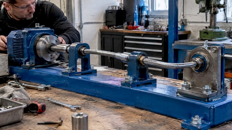
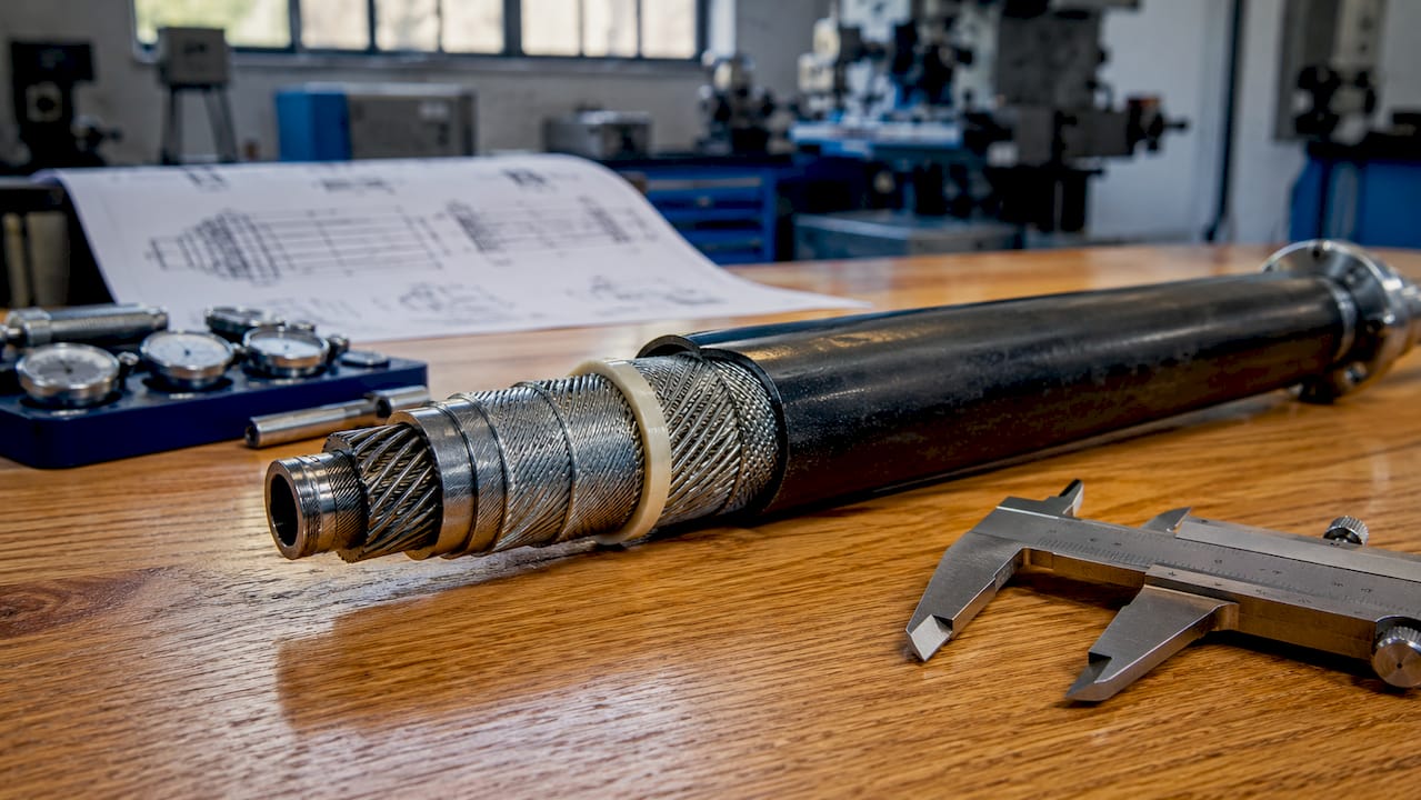
Custom shaft configurations are engineered designs that define geometry, material, tolerances, and interface features to meet specific torque transmission and mechanical integration requirements. Unlike catalog shafts, a custom configuration accounts for every load case, mounting constraint, and interface standard relevant to the application. Design engineers working in industrial manufacturing, aerospace actuation, and precision drive systems rely on these specifications to achieve reliable performance where standard components fall short. Understanding shaft configurations at this level is the foundation for specifying components that perform correctly from the first assembly. This article covers the core design parameters, shaft types, manufacturing processes, and assembly integration principles that govern custom shaft engineering.
What design parameters define custom shaft configurations?
Custom shaft configurations are defined by four primary parameter groups: geometry, material, tolerances, and interface features. Each group directly affects torque capacity, fatigue life, and assembly compatibility.
Shaft geometry
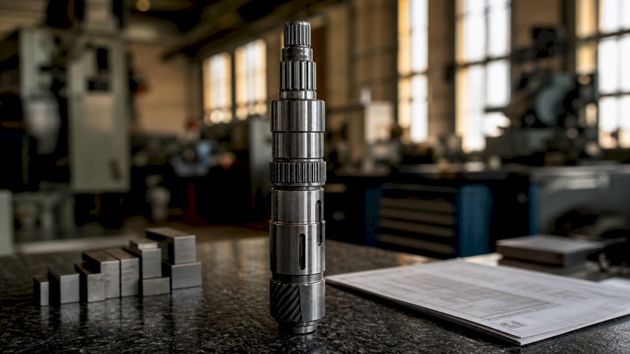
Shaft geometry includes stepped diameters, shoulder fillets, spline profiles, and keyway slots. Stepped diameters allow a single shaft to serve multiple functions, such as supporting a bearing at one diameter while driving a gear at another. Shoulder fillets are not merely cosmetic. Increasing the fillet r/d ratio from 0.02 to 0.1 reduces the stress concentration factor from approximately 2.7 to 1.5, which roughly halves peak stress at the shoulder and extends fatigue life significantly. Spline profiles, including involute and straight-sided types, distribute torque across multiple contact lines rather than concentrating it at a single keyway.
Material selection
Material choice sets the upper limits for strength, corrosion resistance, and machinability. Alloy steels such as 4140 and 4340 are standard for high-torque shafts because of their combination of tensile strength and toughness. Stainless steel grades like 17-4 PH are specified where corrosion resistance is required, such as in food processing or marine environments. Aluminum alloys are used where weight is a primary constraint, though their lower yield strength limits torque capacity. The material must be selected before tolerances are finalized because heat treatment affects dimensional stability.
Precision tolerances and surface finish
Tolerance specification is where many shaft designs fail in practice. Specifying a bearing journal as “40 mm ±0.01” does not communicate fit intent to a machinist or inspector. Using ISO fit designations such as k6 or m6 clearly defines the interference fit required to prevent bearing creep and fretting. Surface finish for rolling bearing journals requires Ra 0.8 µm or better. For high-speed spindle applications, precision CNC grinding can achieve concentricity tolerances as tight as 0.02 mm, compared to the 0.05 mm typical of standard turning operations.
Interface features
Interface features include threads, keyways, splines, and cross-drilled holes. Each feature introduces a stress concentration and a manufacturing operation. Threads cut into a shaft reduce the effective cross-section and create a notch effect. Keyways require broaching or milling and must be positioned relative to other features with care to avoid overlapping stress fields. Custom shaft procurement requires submission of 2D or 3D CAD files in formats such as STP, STEP, or XT to communicate all interface features accurately to the manufacturer.
Pro Tip: Specify ISO fit classes on every bearing and gear journal in your drawing, not just nominal dimensions with bilateral tolerances. This single practice eliminates the most common source of premature bearing failure in custom shaft assemblies.
How do different types of custom shafts compare?
Custom shaft designs fall into several distinct categories, each suited to specific load conditions and installation environments.
Shaft type comparison
| Shaft type | Primary function | Typical application |
|---|---|---|
| Stepped shaft | Multiple diameter zones for bearing and gear interfaces | Gearboxes, electric motor rotors |
| Spline shaft | Distributed torque transmission with axial sliding | Aerospace flap and slat drives, machine tool spindles |
| Hollow shaft | Reduced weight with internal routing capability | Robotics, valve override actuators |
| Threaded shaft | Axial force generation or adjustment | Linear actuators, clamping systems |
| Cam shaft | Timed rotary-to-linear motion conversion | Engine valve trains, indexing mechanisms |
Live shaft vs. dead shaft configurations
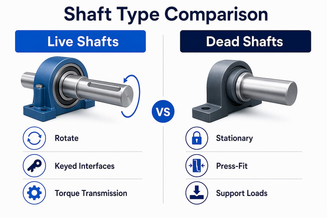
Live shafts rotate with the driven component and require keyed or splined bore interfaces at every attachment point. Dead shafts remain stationary while the surrounding component rotates on bearings mounted to the shaft. This distinction fundamentally changes the bearing selection, lubrication requirements, and maintenance access design. In crane wheel assemblies and conveyor systems, dead shaft configurations simplify wheel replacement because the shaft stays in place during service. Live shaft configurations are standard in gearbox output stages and motor drive trains where the shaft must transmit torque continuously.
Aerospace actuation applications
Aerospace actuation systems impose the most demanding combination of requirements on shaft configurations. Thrust reverser actuation shafts must transmit high torque in confined nacelle spaces while tolerating thermal cycling and vibration. Flap and slat drive shafts often use spline interfaces at both ends to allow axial float during wing flexure. Valve override shafts in hydraulic systems require hollow configurations to route fluid or electrical signals through the shaft bore. Synchronization shafts in multi-actuator systems must maintain angular position accuracy across the full operating temperature range. Each of these contexts requires a shaft configuration designed from the load case outward, not selected from a catalog.
- Thrust reverser shafts: high torque, confined space, thermal cycling
- Flap and slat drives: spline ends, axial float tolerance, corrosion resistance
- Valve override shafts: hollow bore, compact diameter, high torsional stiffness
- Synchronization shafts: angular accuracy, multi-span support, minimal runout
What manufacturing processes ensure precision in custom shafts?
Manufacturing process selection determines whether a shaft meets its tolerance requirements in production, not just in the prototype phase.
- CNC turning establishes the primary diameter profile, shoulder locations, and thread features. Modern multi-axis CNC lathes hold dimensional tolerances of ±0.01 mm on diameter in routine production.
- CNC milling cuts keyways, flats, and cross-holes. Milling operations are sequenced after turning to avoid disturbing the datum surfaces used for turning.
- Cylindrical grinding achieves the final bearing journal dimensions and surface finish. Precision grinding delivers tolerances as tight as ±0.002 mm and surface finishes down to Ra 0.2 µm for high-speed bearing journals.
- Heat treatment is performed between rough machining and finish grinding. Carburizing, nitriding, or through-hardening increases surface hardness and fatigue resistance. Distortion from heat treatment is corrected in the finish grinding stage.
- Inspection with CMM (coordinate measuring machine) verifies concentricity, runout, and positional tolerances on all critical features. Surface roughness measurement confirms Ra values at bearing and seal journals.
Batch size affects process selection. Prototype quantities of one to five parts are typically produced on universal CNC centers with manual setup. Production batches of 50 or more parts justify dedicated fixtures and process sheets that reduce setup variation. Rotor shafts for electric drives illustrate this well: they integrate bearing support and gear interface functions in a single component, requiring precise manufacturing specifications across every feature to maintain assembly chain quality.
Pro Tip: Request a first-article inspection report with CMM data on every new shaft design before approving production. A single out-of-tolerance feature on a prototype is far less costly than a batch of non-conforming parts discovered at assembly.
How should custom shaft configurations be integrated into mechanical assemblies?
Shaft configuration does not end at the shaft drawing. The shaft must be designed in coordination with the gears, bearings, couplings, and housings it interfaces with.
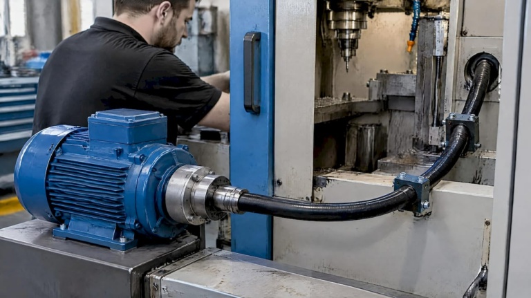
Gear tooth profile selection directly determines the axial forces acting on the shaft. Helical gears generate axial thrust loads that require angular contact or tapered roller bearings. Bevel gears impose combined radial and axial loads that affect shaft bending moments across the full support span. Designing the shaft without knowing the gear type and tooth geometry produces an undersized or incorrectly supported shaft.
Operating speed is a critical integration parameter. Shaft operating speed should remain below 75–80% of the first critical speed to avoid resonant vibration. The first critical speed depends on shaft stiffness, mass distribution, and bearing span. Reducing the bearing span or increasing shaft diameter both raise the critical speed. For high-speed spindle shafts, this calculation must be performed before finalizing the shaft geometry.
The following design practices reduce assembly integration failures:
- Design shoulder fillets to the largest radius the adjacent component allows. A larger fillet radius directly reduces the stress concentration factor at that transition.
- Specify bearing fits using ISO fit classes, not bilateral tolerances, to prevent creep under load.
- Apply bending and torsion shock load factors of 1.5 to 3.0 for shafts in start-stop or reversing load conditions. These factors account for peak stresses that static analysis misses.
- Coordinate coupling selection with shaft end geometry. A flexible coupling compensates for minor misalignment but does not eliminate the need for accurate shaft alignment during installation.
- For custom drive shaft applications, confirm that the shaft end interface matches the coupling bore and keyway standard used in the rest of the drive train.
Key Takeaways
Custom shaft configurations require coordinated specification of geometry, material, ISO fit tolerances, and interface features to achieve reliable torque transmission across the full service life of the assembly.
| Point | Details |
|---|---|
| ISO fit classes prevent bearing failure | Specify k6 or m6 fit classes on bearing journals instead of bilateral tolerances to prevent creep and fretting. |
| Fillet radius controls fatigue life | Increasing the shoulder fillet r/d ratio from 0.02 to 0.1 reduces the stress concentration factor from 2.7 to 1.5. |
| Operating speed must stay below critical speed | Keep shaft speed below 75–80% of the first critical speed to avoid resonant vibration in service. |
| CAD files drive procurement accuracy | Submit 2D or 3D CAD files in STP or STEP format to communicate all interface features to the manufacturer. |
| Shock factors are required for fatigue design | Apply shock load factors of 1.5 to 3.0 for shafts in reversing or start-stop load conditions. |
What I have learned from specifying custom shafts in demanding applications
The most consistent mistake I see in custom shaft specifications is treating the shaft as an isolated component. Engineers finalize the gear design, select the bearings, and then design the shaft to fit what remains. The shaft ends up with a geometry driven by clearance constraints rather than load paths. The result is a shaft with undersized fillets, bearing journals specified with bilateral tolerances instead of ISO fits, and a critical speed that was never calculated.
The second pattern I see is over-reliance on material upgrades to solve geometry problems. Switching from 4140 to 4340 steel adds cost and lead time but does not fix a stress concentration at a sharp shoulder. The fillet radius change costs nothing in material and delivers a measurable reduction in peak stress. Geometry changes should always be evaluated before material upgrades.
Aerospace actuation applications have reinforced one principle above all others: the shaft drawing must be complete before any manufacturing begins. Incomplete drawings produce shafts that require rework or replacement. In confined nacelle or wing environments, a shaft that does not fit costs far more than the part itself. The investment in a thorough first-article inspection, including CMM verification of every critical feature, pays back immediately when the shaft fits correctly on the first installation.
The direction I see custom shaft technology moving is toward tighter integration between shaft design and system simulation. Finite element analysis of the full assembly, including the shaft, bearings, housing, and gear mesh, is becoming standard practice for high-value applications. This approach catches resonance and fatigue issues before the first prototype is cut. Engineers who adopt this workflow earlier in the design process consistently produce more reliable assemblies with fewer revision cycles.
— Uli
Biax-flexwellen custom shaft solutions for industrial engineers
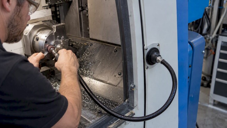
Biax-flexwellen, part of Schmid & Wezel GmbH, designs and manufactures flexible shaft and drive solutions for applications where rigid shafts cannot reach or fit. The engineering team supports machine builders and industrial manufacturers with technical guidance on torque and RPM requirements, coupling interfaces, and shaft geometry for deburring, grinding, polishing, and finishing processes. For engineers evaluating how flexible shaft technology fits into a custom drive train, the machine design efficiency resource covers the functional principles in detail. Engineers with specific torque, speed, or interface requirements can submit technical inquiries directly through the Biax-flexwellen contact page to receive application-specific guidance.
FAQ
What is a custom shaft configuration?
A custom shaft configuration is a shaft design specified to meet exact geometry, material, tolerance, and interface requirements for a particular application. It differs from a standard catalog shaft in that every feature is defined by the load case and assembly constraints.
Why are ISO fit classes required on bearing journals?
ISO fit designations such as k6 or m6 define the interference or clearance between the shaft and bearing bore. Specifying only a nominal dimension with bilateral tolerances does not communicate fit intent and leads to bearing creep or fretting in service.
How tight can CNC machining tolerances be on custom shafts?
Precision CNC grinding achieves tolerances as tight as ±0.002 mm on diameter and surface finishes down to Ra 0.2 µm on bearing journals. Standard CNC turning holds approximately ±0.01 mm in routine production.
What is the difference between a live shaft and a dead shaft?
A live shaft rotates with the driven component and transmits torque through keyed or splined interfaces. A dead shaft remains stationary while the surrounding component rotates on bearings mounted to the shaft, which simplifies maintenance in conveyor and crane wheel applications.
How does shaft speed relate to critical speed in assembly design?
The operating speed of a shaft should remain below 75–80% of its first critical speed to avoid resonant vibration. The first critical speed depends on shaft stiffness, mass distribution, and bearing span, and must be calculated during the shaft design phase.
Recommended
- Custom flexible shaft design explained: engineer better solutions
- Custom Flexible Shaft Configuration Guide for Engineers
- Shaft Design Considerations for Engineers: A Technical Guide
- What Is Custom Shaft Engineering for Industrial Design – BIAX Flexwellen
Related Topics
Send your spec inquiry
Custom flexible shafts for your application — we quote within 1 working day.