Flexible Shaft Length Selection: Routing, Bend Radius and Load
26 October 2026The length of a flexible shaft is the length of the routed path between the two connection points, plus the allowances for end fittings, tolerances and movement. A straight-line distance from drive to driven unit is not a usable figure. The correct length follows from the installed geometry, the minimum bend radius, the torque and speed requirement, and the stack-up of the end connections.
This article describes how to derive the length for industrial and aerospace-type installations, such as actuation and synchronization shafts in confined structures, and how to verify the result before release.
TL;DR
- Measure the length along the actual routing path, not the straight-line distance, and add allowances for end fittings, axial movement and tolerances.
- Distribute direction changes over as much shaft length as possible. Minimum bend radius is a hard limit, not a target.
- Longer shafts have higher torsional windup and more friction along the casing. Torque, speed and positioning accuracy must be checked against the final length.
- Verify the selection with a routed mock-up or prototype under the real load cycle before series release.
- Provide complete data (path, radius, torque, speed, duty, environment) with the inquiry so the configuration can be checked against the length.
Table of Contents
- What “length” means for a flexible shaft
- Step 1: Define the routing path
- Step 2: Respect the minimum bend radius
- Step 3: Add allowances to the path length
- Step 4: Check torque, speed and windup against the length
- Step 5: Consider environment and installation conditions
- Step 6: Verify the selected length
- Common selection errors
- How BIAX can support the selection
- Perspective: length is a system parameter
- What to include in an inquiry
- FAQ
- Sources
What “length” means for a flexible shaft
A flexible shaft transmits rotation through a wound core. In most designs the core runs inside a protective sheath or casing. Several lengths are therefore in play, and drawings regularly confuse them:
- Path length: the distance along the centerline of the routed shaft from one interface to the other.
- Core length: the length of the rotating element, which is usually longer than the sheath so that it can engage the end fittings.
- Sheath or casing length: the stationary outer part, which carries the clamping or mounting points.
- Overall length: the finished assembly, including end fittings, couplings and any stops.
A specification should state which of these it refers to, and where the reference points are (face of the fitting, center of a mounting hole, end of the square or keyed drive). Ambiguity here is a common source of shafts that arrive a few millimeters too short or too long, with no way to correct them on site.
Step 1: Define the routing path
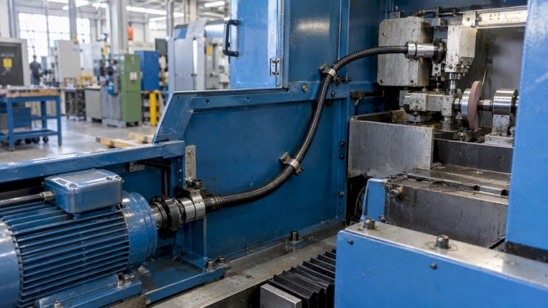
The starting point is the three-dimensional route the shaft takes through the installation. For aerospace-type structures this might be a synchronization shaft between two actuators on a flap or slat system, a drive to a valve override, or a shaft inside a confined nacelle area. In industrial machines it can be a drive to a spindle that sits behind a fixture or inside a housing.
Collect the following:
- Position and orientation of both end interfaces, including the allowed tolerance.
- Obstructions: brackets, structure, hoses, harnesses, and heat sources.
- Location and direction of every change in direction.
- Whether either end moves relative to the other (articulated tool head, deploying surface, swinging arm).
- Where the sheath can be supported or clamped.
From this, create a centerline in CAD and measure its developed length. If the model has no shaft, a flexible spline or sweep with the minimum radius enforced gives a better estimate than a hand-drawn arc.
Step 2: Respect the minimum bend radius
Bend radius is the main geometric constraint on length. A tighter bend increases friction between core and sheath, raises the stress in the wire layers, and reduces the torque the shaft can transmit. It also shortens service life.
Manufacturers publish minimum radii for each construction. One German supplier of flexible metal shafts, for example, states an approximate minimum bend radius of 20 times the outside diameter for its design and lists separate product-specific values. That figure is not transferable to other constructions. It does show the scale: a shaft assembly with a 10 mm outside diameter and a 20 × OD rule would need a 200 mm radius, which is large compared with many equipment bays. The value for the specific shaft must come from the manufacturer’s data.
Two practical rules follow:
- Use the largest radius the space allows, not the smallest the datasheet permits. Static installations may be allowed a tighter radius than dynamic ones, and loaded bends are more critical than unloaded ones.
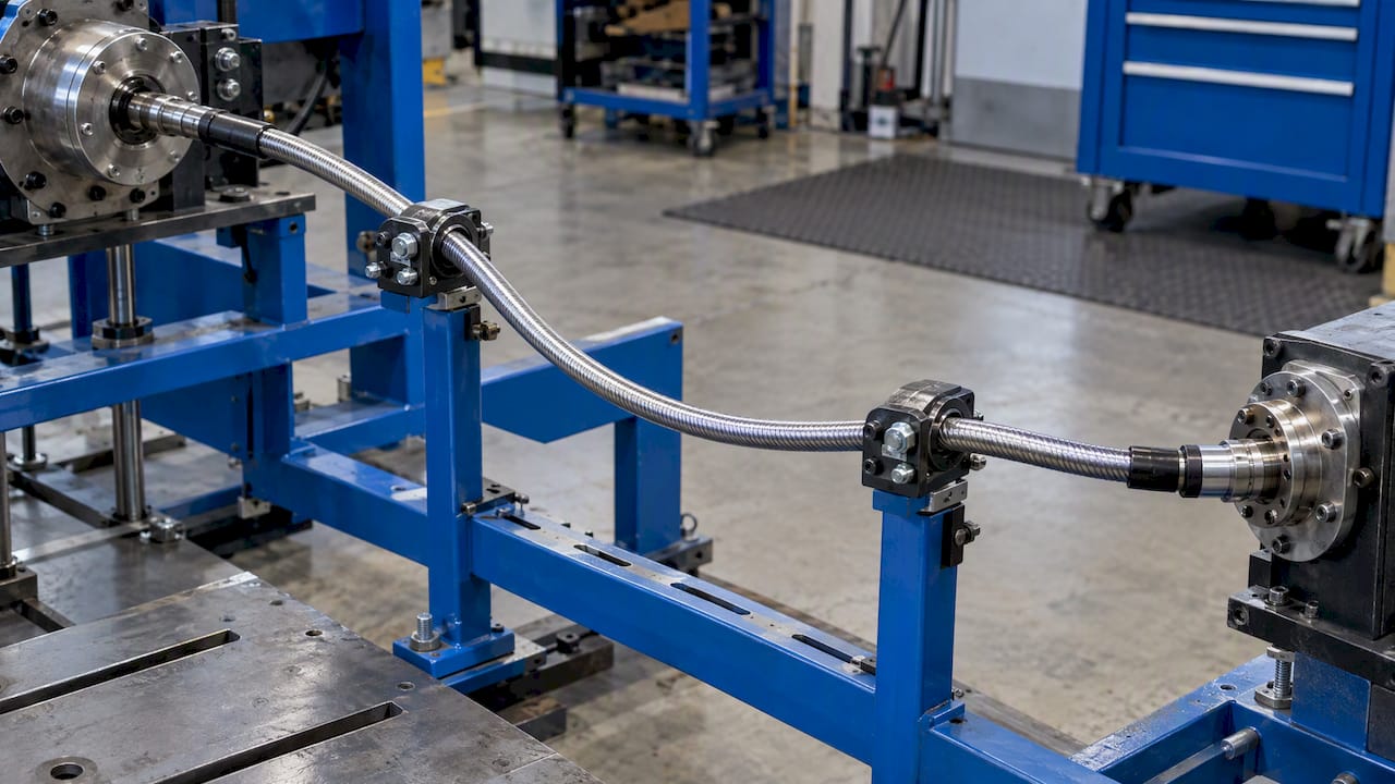
- Spread direction changes over a long length. A total change of 90° taken as one sharp bend is worse than the same change taken as a gradual arc. This also means that very short shafts with large direction changes are often less feasible than a longer shaft with a generous arc.
A longer shaft is therefore sometimes the better choice. It gives room for a larger radius, but it adds windup and friction. The selection is a balance, not a rule of “as short as possible”.
Straight sections at the ends
Most designs require a short straight section at each end fitting before the first bend starts. This keeps the bending stress away from the swaged or crimped connection, where the shaft is stiffened and where fatigue failures typically begin. The required straight length depends on the fitting and the shaft diameter, and it must be added to the path length. A shaft that bends directly out of the fitting will not meet its life expectation, even when the radius is nominally within limits.
Step 3: Add allowances to the path length
Once the developed centerline length is known, the ordered length is built up from several contributions:
| Contribution | What to consider |
|---|---|
| Developed path length | Centerline between interfaces at nominal position |
| End fitting engagement | Depth of the square, keyed or splined drive inside the coupling; length of the fitting itself |
| Straight end sections | Length before first bend, as required by the fitting |
| Axial movement | Relative displacement of the two interfaces in operation, in both directions |
| Tolerance stack | Position tolerance of both housings, bracket tolerances, shaft length tolerance |
| Thermal change | Differential expansion between structure and shaft where temperature range is wide |
| Slack for service | Whether the shaft must be removable without moving adjacent units |
The last point matters in maintenance planning. A shaft installed with no slack may only be removable by dismantling the neighboring components. A defined small allowance, within the permitted radius, lets the connection be released and the shaft withdrawn.
Fixed length versus length that can float
In many designs the core is not axially fixed at one end. It is allowed to slide in the fitting, which absorbs length changes when the shaft flexes or the interfaces move. In that case, the core length must cover the full range of movement while still leaving sufficient engagement at the end of the stroke. Where both ends are rigidly fixed, there is no compensation, and the length tolerance must be controlled much more tightly.
Step 4: Check torque, speed and windup against the length
Length is not neutral for performance. As path length grows:
- Torsional windup increases. The core twists under load, so the angle between the input and output grows with length and torque. For synchronization shafts, where two actuators must stay in phase, this angle can be the deciding criterion. For a tool drive, it is usually irrelevant.
- Friction losses increase. More contact between core and sheath means more heat and lower efficiency, especially with many bends.
- Whip and vibration risk increases at high speed. A long, lightly supported shaft at high rotational speed can show uneven running if the sheath is not guided properly.
- Direction of rotation matters. Many flexible shaft designs are optimized for one direction of rotation, because the wire layers tighten or loosen with torque. The permitted direction and the reversal behavior need to be confirmed against the application. A shaft that runs in both directions, as an actuation shaft usually does, needs a construction suited to it.
The practical approach is to define the load case first: nominal torque, peak torque (including jams and stall in actuation systems), speed range, duty cycle and direction. Then, check the candidate construction at the final path length and radius. The torque capacity of a given shaft is stated for defined bend conditions, and it falls when the bend is tighter than the test condition.
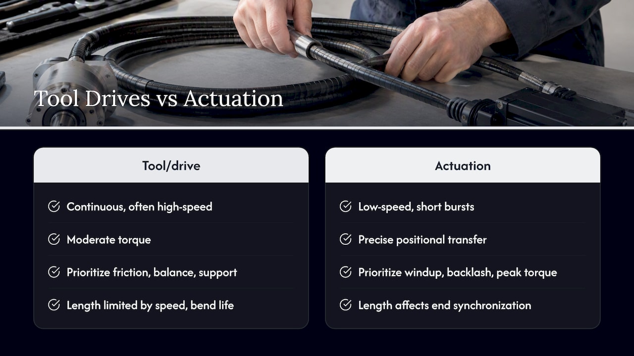
Tool drives versus actuation shafts
The two main groups behave differently, and the length selection reflects that.
Tool and drive shafts run continuously, often at high speed, with moderate torque. Priorities: low friction, balanced running, adequate support, and heat control. Length is typically limited by speed and bending life. For deburring, grinding and polishing, the length is often also a handling question: how far the tool head must reach and how much shaft is loose in the operator’s or robot’s range of motion. BIAX describes its drive and tool shafts for speeds up to 50,000 rpm in this category.
Actuation shafts transmit torque at low speed, often in short bursts, and they may need precise positional transfer. Priorities: windup, backlash, peak torque and fatigue under rare but heavy loads. Examples are flap and slat drive lines, thrust reverser actuation synchronization, and manual or powered valve override. Here, length affects whether two ends stay synchronized within tolerance. The actuation shaft range covers this type of application.
Step 5: Consider environment and installation conditions
The operating environment affects the construction, and through it the achievable length and bend radius:
- Temperature range. Lubricant, sheath material and any polymer liner have limits. High temperature near engines or hydraulic components changes friction and life.
- Contamination. Fluids, dust and swarf can enter the casing at the ends. Sealing at the fittings and the sheath material must be matched to the medium.
- Vibration. Continuous vibration of the structure causes fretting at clamps and fittings. Clamp spacing and clamp material need to be defined.
- Corrosion. Material selection and surface treatment of the core and sheath have to match the exposure.
- Space for assembly. The shaft has to be installed through the available openings without exceeding its bend radius during assembly. A radius that is acceptable in the final position may be exceeded when the shaft is threaded into place.
For aerospace parts the qualification requirements of the customer and the certification authority apply on top of the above. The shaft supplier can provide design data, but qualification evidence and compliance with the customer’s specifications are agreed per program.
Step 6: Verify the selected length
Calculation should be confirmed with hardware. A short verification sequence:
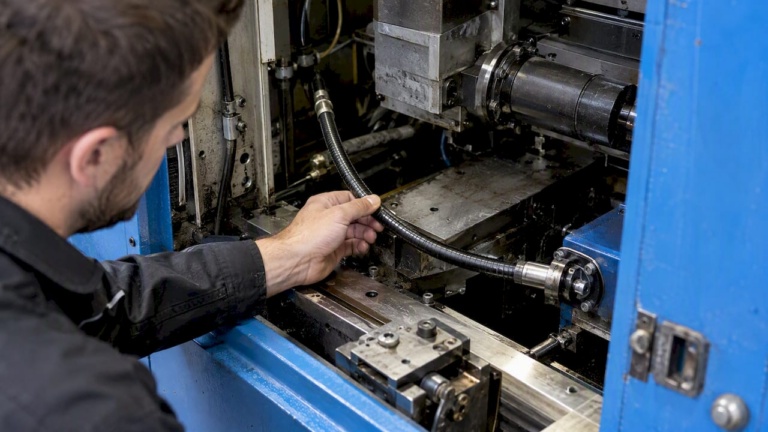
- Routed mock-up. Install a shaft sample in the real geometry or a representative fixture. Check the achieved radii, the straight end lengths and the fit of all clamps. Mark the core position at both ends.
- Movement check. Cycle the system through its full range of motion and check that the core never bottoms out or loses engagement.
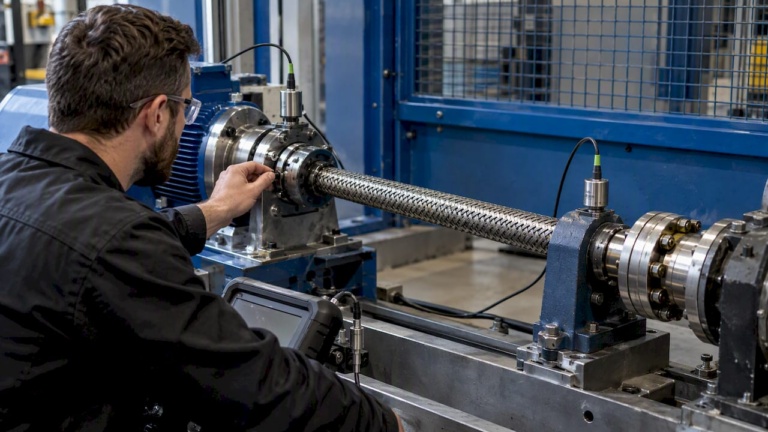
- Windup measurement. Apply nominal and peak torque at the output and measure the angular deflection. Compare it with the system requirement.
- Thermal check. Run the nominal duty cycle and monitor the sheath temperature, especially at bends.
- Endurance test. Run the expected number of cycles or operating hours under load, then inspect the core, sheath and fittings for wear.
- Removal and reinstallation. Confirm the shaft can be serviced as planned.
Common selection errors
- Straight-line length used as the order length. The shaft is too short once routed, or it is forced into tight bends.
- Bend radius taken from the nominal value without end sections. The first bend begins at the fitting and causes early fatigue.
- No allowance for movement or tolerances. The core bottoms out at one end of the stroke.
- Excess length stored in a coil. A loop of surplus shaft creates a small radius, extra friction and unpredictable windup.
- Torque rating used without considering the bend. The catalog value applies to a defined condition, not to every installation.
- Windup ignored in synchronization. Two shafts of different length in one system produce different angular deflection under the same torque.
- Unsupported long runs at high speed. Uneven running and heat result.
- Mounting points chosen after the shaft. Clamp positions define the real radii and should be set during layout, not in assembly.
How BIAX can support the selection
BIAX Flexwellen manufactures standard and custom flexible shafts and supports design engineers with configuration of torque, speed, coupling interface and shaft construction. For applications with a defined routing, a prototype or small-batch configuration can be checked against the real geometry before series production. The relevant range is described under special solutions and prototypes. Background on the interfaces is available in the guide to coupling interfaces in machining, and on dimensioning in the custom flexible shaft configuration guide. Tool holder parameters for aerospace use are covered in the article on torque, RPM and bend radius specifications.
Perspective: length is a system parameter
We see length questions most often arrive as a single number: “We need a shaft of 600 mm.” In nearly every case the number was taken from a straight-line measurement, and the routed path turns out to be different. The first step in our review is therefore to ask for the routing, the radii and the end interface details, not the length.
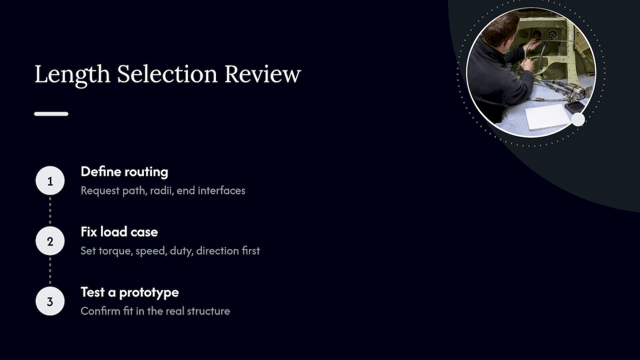
The second observation is that length cannot be chosen independently of the load case. A configuration that works at 400 mm may show too much windup at 900 mm, and a shaft that is comfortable at moderate speed may need guidance at high speed. We prefer to fix torque, speed, duty and direction first, then compare the available constructions at the real path length.
Third, a mock-up saves more time than any additional calculation. Small deviations in routing and clamp positions change radii, and radii dominate life. Where the installation allows it, a prototype shaft in the real structure gives the quickest confirmation, and our prototype and small-batch capability exists for that purpose.
— Uli
What to include in an inquiry
A length can be confirmed quickly when the following data is available:
- Drawing or 3D model with both interfaces and the intended routing.
- Smallest radius available at each bend, and the length of straight sections at the ends.
- Required torque (nominal and peak), speed range, duty cycle and direction of rotation.
- Relative movement of the end interfaces and the required tolerance.
- Coupling or connection type at each end.
- Ambient temperature, media exposure and vibration profile.
- Required positional accuracy or maximum angular deflection, where synchronization applies.
- Quantity, from prototype to series.
Standard shafts sold by the meter, as described under flexible shaft cores by the meter, suit applications where the engineer cuts and finishes the length. Finished assemblies with defined fittings are better suited to constrained routing.
FAQ
How is the length of a flexible shaft measured?
The length is measured along the centerline of the routed shaft between the two reference points of the interfaces. The drawing must state whether it refers to the core, the sheath or the finished assembly, and where the reference points on the fittings are. Allowances for end engagement, straight sections, movement and tolerances are added to the developed path length.
Is a shorter flexible shaft always better?
Not necessarily. A shorter shaft has less windup and friction, but it may force a tighter bend radius than the construction permits. A somewhat longer shaft with a larger, gradual radius can give a longer service life. The selection is checked against both the geometry and the load case.
What bend radius should be used when selecting the length?
The minimum bend radius is defined by the manufacturer for each construction. One supplier, for example, gives an approximate value of 20 times the outside diameter for its design. For any other shaft, the value from its own data sheet applies. The largest radius that the installation permits should be used, and direction changes should be spread over a long length.
Does shaft length affect the torque that can be transmitted?
Length itself mainly affects windup and friction, while the bend radius and number of bends affect the usable torque. The torque rating applies to a defined test condition, and a tighter or more frequent bending reduces the available capacity. The final configuration should be checked at the real path length, radius and speed.
What data is needed to confirm a length with the manufacturer?
The routing geometry, minimum radii, end interface type, torque and speed profile, duty cycle, direction of rotation, movement of the interfaces and environmental conditions are needed. With this information, the construction and length can be reviewed together. Inquiries can be sent through the BIAX Flexwellen website, where the contact options are available.
Sources
Recommended
- Custom Flexible Shaft Configuration Guide for Engineers
- Custom flexible shaft design explained: engineer better solutions
- Shaft Design Considerations for Engineers: A Technical Guide
- How to Select Flexible Shafts for Precision Machinery
Related Topics
Send your spec inquiry
Custom flexible shafts for your application — we quote within 1 working day.