Balancing a Flexible Shaft: Methods, Standards and Limits
28 October 2026A flexible shaft drive is balanced as a system, not as a single part. Unbalance in the shaft, end fittings, couplings and driven element excites vibration at rotational frequency, and the elastic deformation of a slim rotor can amplify it with speed. Whether a drive needs balancing, in how many planes, and where, depends on operating speed, length, support conditions and the proximity to critical speeds. This article sets out the principles, the measurement and correction methods, the relevant standards for Germany and the installation practices that keep vibration low. It is written for design and aerospace engineers who work with thrust reverser drives, flap and slat actuation, valve override systems, synchronization shafts and other confined installations.
TL;DR
- Unbalance is an asymmetric mass distribution about the rotation axis. It produces rotating forces that appear as vibration at 1X running speed.
- A slim flexible rotor deforms elastically with speed. Balancing at low speed alone may therefore be insufficient, and final balancing may have to be done at operating speed or on site.
- Single-plane balancing corrects static unbalance. Two planes are needed for couple or dynamic unbalance. Rotors operating close to a critical speed need multi-plane or modal methods.
- ISO 21940-12 covers procedures and tolerances for rotors with flexible behavior. ISO 21940-13 covers in-situ balancing of installed rotors.
- Routing, bend radius, support spacing and maintenance condition determine much of the vibration behavior before any balancing weight is added.
Table of Contents
- What balancing means for a flexible shaft drive
- When a flexible shaft drive needs balancing
- Static, dynamic or multi-plane balancing
- Measurement and correction
- Standards and requirements in Germany
- Installation and operating practice
- Our view on balancing in flexible shaft drives
- Custom drives and configurations
- FAQ
- Contact
- Sources
What balancing means for a flexible shaft drive
Unbalance exists when the mass distribution of a rotor is not symmetrical to its shaft axis. The result is a set of rotating forces and moments that excite vibration at rotational frequencies, as VDI 3839 Part 2 describes.
For a flexible shaft, the term needs a precise reading. The flexible core transmits torque along a curved path. It is not a stiff rotor with defined journals and bearing planes. The elements that carry concentrated mass and can therefore generate unbalance are typically:
- the end fittings and couplings at the drive and driven side,
- keys, keyways, set screws and other interface features,
- the driven element, such as a gearbox input, a tool or an actuator,
- the core itself, where manufacturing deviations, material non-homogeneity or eccentricity are present.
VDI 3839 Part 2 lists manufacturing deviations, material non-homogeneity and eccentricity as sources of unbalance, and adds that service conditions can introduce further unbalance after manufacture. So a drive that was acceptable at delivery can drift.
Symptoms of an unbalanced drive
Fluke describes imbalance as elevated 1X rotational vibration in the radial and tangential directions, with little corresponding increase in the axial direction. Severity is judged against a baseline amplitude (Fluke, vibration diagnosis). In practice, an engineer looks for:
- A dominant peak at running speed in the spectrum, in the radial plane.
- Vibration amplitude that rises with speed and changes with the shaft routing.
- Phase that is stable between measurements, which separates unbalance from looseness or misalignment indications.
- Noise, housing vibration or fretting at fittings that develops gradually.
A baseline measured on a healthy drive at commissioning is the reference for all of these. Without it, a 1X peak has no context.
When a flexible shaft drive needs balancing
The need depends on a small group of parameters.
| Parameter | Effect on balancing need |
|---|---|
| Operating speed | Unbalance force grows with the square of speed. Elastic deformation becomes significant as speed approaches a critical speed. |
| Length and slenderness | Longer, slimmer shafts deform more and carry unbalance along their length, not only at the ends. |
| Construction | Core design, sheath, end fitting mass and interface features determine where mass can be asymmetric. |
| Couplings and fittings | Keys, keyways and fits introduce eccentricity even when individual parts were balanced. |
| Complete drive assembly | Bearings, supports and foundations change the deformation and the effective critical speeds. |
VDI 3839 Part 2 states that slim flexible rotors can develop speed-dependent elastic deformation that amplifies unbalance. Where the installation, the bearings or the foundation influence that deformation, final balancing may need to be done on site under operating conditions.
The Texas A&M Turbomachinery Laboratory lists fouling or deposits, uneven heating, rotor bow, material loss from rubs and changing component balance as operational causes of unbalance (Texas A&M, rotor balancing tutorial). Their rotor balancing guide adds that assembly tolerances and key and keyway conventions can create unbalance even when the shaft and rotor components were individually balanced (Texas A&M, rotor balancing guide). For a flexible shaft, this matters at every coupling and fitting.
Fluke names thermal growth, uneven wear, missing balance weights, bent shafts, manufacturing defects and incorrect assembly or replacement parts as common causes of dynamic imbalance (Fluke, dynamic unbalance). Replacement parts deserve attention in maintenance planning: a fitting swapped without checking its mass and fit can change the balance state of the whole drive.
Aerospace installation contexts
The following applications share confined routing, long transmission paths or multiple driven points:
- Thrust reverser actuation: several actuators driven through shafts, with defined torque and a limited installation envelope.
- Flap and slat actuation: synchronization shafts that couple multiple actuation points along a span.
- Valve override systems: manual or remote actuation through a flexible shaft routed around obstacles.
- Synchronization shafts in general: two or more outputs required to move together.
In these systems the requirement is often not high speed but low vibration at the specified speed range, predictable torque transmission and no resonance in the operating band. Speed range, support spacing and fitting mass are therefore design inputs, not afterthoughts. Our article on flexible shaft vibration priorities in aerospace covers the vibration side of these design decisions in more detail.
Static, dynamic or multi-plane balancing
The correct method follows from the unbalance type and the rotor’s behavior at speed.
Unbalance types
ISO 21940-1 distinguishes static, moment (couple) and dynamic unbalance, and it describes flexible behavior as a speed-dependent movement of mass in which unbalance bends the rotor (ISO 21940-1:2019). Siemens explains the practical consequence: static unbalance is a displaced center of mass, couple unbalance requires correction in two planes, and dynamic unbalance combines both (Siemens, balancing).
| Unbalance type | Cause | Correction |
|---|---|---|
| Static | Center of mass displaced from the axis | One correction plane |
| Couple (moment) | Two equal and opposite unbalances in different planes | Two correction planes |
| Dynamic | Combination of static and couple | Two correction planes |
| Flexible rotor unbalance | Distributed unbalance that deforms the rotor with speed | Multi-plane or modal balancing |
Rigid or flexible behavior
The Texas A&M guide describes a rotor as flexible when it operates at approximately 70 to 75 percent of its critical speed or above. Such rotors require multi-plane balancing, not the ordinary two-plane approach used for rigid rotors (Texas A&M, rotor balancing guide).
This gives a workable decision path:
- Determine the first critical speed of the installed drive, including the support conditions.
- Compare it with the maximum operating speed. If operation stays well below roughly 70 percent of the critical speed, rigid-rotor methods are generally applicable to the end-fitting assemblies.
- If operation approaches or exceeds that range, treat the shaft as flexible and plan multi-plane or modal balancing.
- Check whether the installation influences deformation. If so, plan for balancing in situ.
VDI 3839 Part 2 recommends balancing slim flexible rotors at operating speed, because speed-dependent elastic deformation amplifies unbalance. Where the installation support affects deformation, final balancing may be performed in situ by competent personnel.
A practical point for flexible shaft assemblies: the end-fitting and coupling subassemblies can usually be balanced as rigid components before assembly. The flexible core and its routing are the part whose behavior is determined only by the installed system.
Measurement and correction
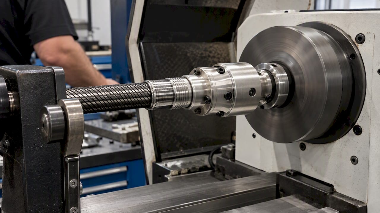
Components balanced on a machine
Fittings, couplings and tool-side components can be balanced on a balancing machine as rigid parts. This step removes the unbalance that is under direct control. It does not capture the effect of the installation, which is the limitation of off-system balancing.
In-situ balancing
DIN Media states that in-situ balancing preserves the dynamic properties of the installed bearings, support structure and complete rotor train, properties that a separate balancing machine can miss (DIN ISO 21940-13). The standard covers the conditions for in-situ balancing, required instrumentation, safety implications, and reporting and recordkeeping for medium and large rotors in their own bearings. Its scope is stated for medium and large rotors, so engineers should check whether its provisions fit a compact flexible shaft drive or serve only as a framework.
Instrumentation and method
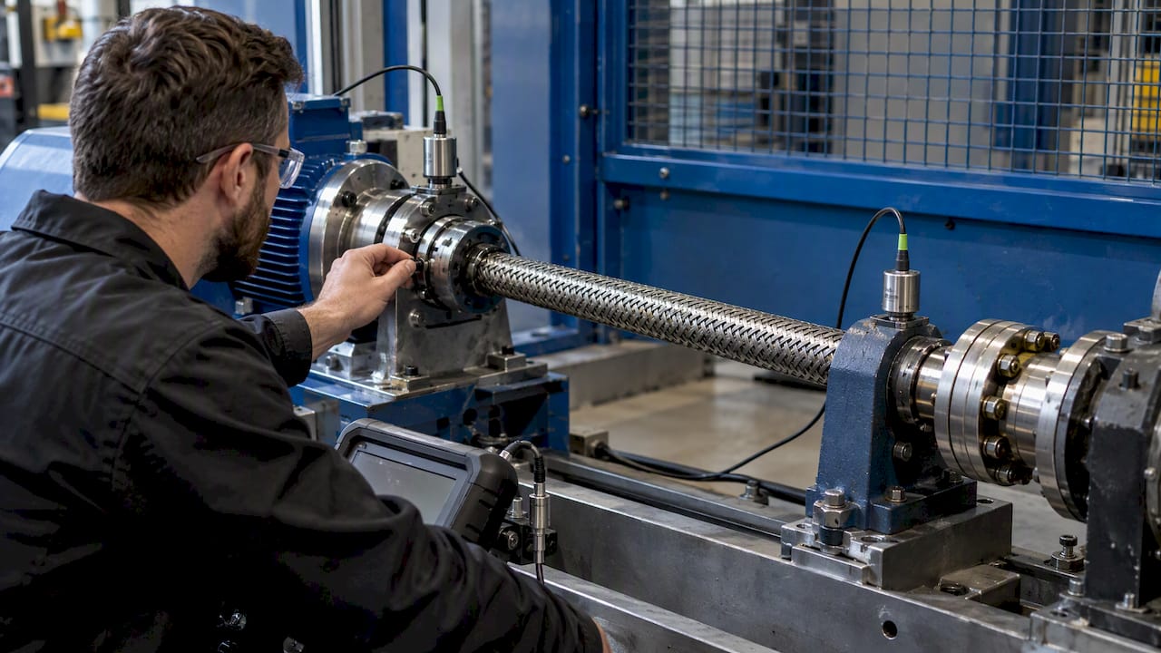
Field balancing generally follows an influence-coefficient sequence:
- Measure the baseline vibration amplitude and phase at running speed.
- Add a known trial mass at a defined position and angle.
- Measure the change in amplitude and phase.
- Calculate the correction mass and angle from the observed response.
- Apply the correction, then verify by measuring again.
For flexible rotors, systems such as those described by Hofmann support modal balancing and influence-coefficient correction, evaluate unbalance-induced and twice-speed vibration, display polar or XY plots and predict the effect of corrections (Hofmann, flexible rotor balancing data sheet). The prediction function reduces the number of trial runs, which matters when access to the installed system is limited.
Measurement points should sit close to the supports and, where accessible, near the coupling. Record the speed, temperature and load state for each run. Unbalance response changes with all three.
Standards and requirements in Germany
Engineers should verify the following documents for their application.
| Document | Relevance |
|---|---|
| ISO 21940-12:2016-04 (DIN Media) | Procedures and tolerances for rotors with flexible behavior. It replaces ISO 11342 and its corrigendum. |
| ISO 21940-12:2016 (ISO) | Covers procedures, final-balance assessment and balance-quality guidance. It is guidance rather than an acceptance specification and allows deviations for specialized equipment. Confirmed current in 2025. |
| DIN ISO 21940-13 | Balancing of installed rotors in their own bearings. |
| DIN ISO 21940-23 | Enclosures and protective measures for balancing-machine measuring stations, including hazards, safety requirements and verification. |
| VDI 3839 Part 2 | Instructions on measuring and interpreting vibrations, including slim flexible rotors. |
Because ISO 21940-12 is guidance and allows deviations, the balance quality for an aerospace drive normally comes from the customer specification, the system-level vibration requirement and the applicable certification basis. The standard supports that definition. It does not replace it.
Two regulatory frameworks apply on the machine and workplace side. BAuA explains that machinery safety requirements in Germany are implemented through the Product Safety Act and the 9th Product Safety Ordinance, which address applicable machinery, conformity assessment and CE marking (BAuA, machinery). For hand-held or hand-guided equipment driven through flexible shafts, BAuA guidance says employers must assess vibration exposure using actual workplace exposure where possible, account for daily exposure duration and retain measurement documentation for at least 30 years (BAuA, hand-arm vibration). The legal basis and current limit values should be confirmed with the safety department.
Installation and operating practice
Many vibration problems in flexible shaft drives are reduced or avoided by installation, before any balancing correction is considered. VDI 3839 Part 2 notes that installation conditions, bearing elasticity and foundation elasticity can all affect the deformation of a flexible rotor. The same system therefore behaves differently in different mounting conditions.
Routing and bend radius
- Keep the bend radius at or above the value specified for the shaft type. Tight bends raise friction, heat and torsional windup, and they produce non-uniform rotation.
- Avoid bends close to the end fittings. A straight section at each end keeps the load path concentric.
- Avoid S-shaped routing with reversing bends where the layout allows an alternative.
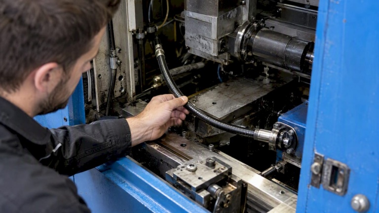
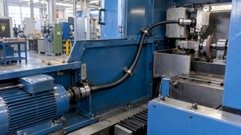
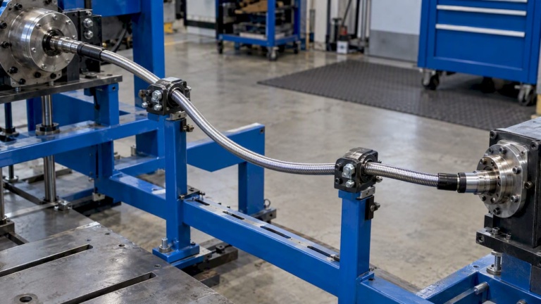
- Support long runs at defined intervals so that the sheath does not whip at speed.
Our torque transmission best practices and the article on flexible shaft design for tight-space finishing address routing constraints and their effect on torque delivery.
Fittings and interfaces
- Check run-out at the coupling interface after assembly.
- Use the key, keyway and fastener convention that was used when the part was balanced. The Texas A&M guide identifies this convention as a source of residual unbalance.
- Record the mass and position of any balance correction so that replacement parts can be matched.
Maintenance
BAuA recommends controlling vibration at the source through substitution and low-vibration equipment, technical measures, maintenance and cleaning programs, and work organization that limits exposure duration. Its prevention hierarchy places elimination or reduction at the source ahead of personal protective equipment.
For drive maintenance this means:
- Measure the vibration baseline after installation and repeat at defined intervals.
- Inspect for contamination, deposits and wear, which change mass distribution.
- Inspect fittings for looseness and fretting.
- Replace worn shafts as a complete, specified assembly, not by mixing components.
The shop-floor practices in a CNC preventive maintenance checklist show how interval-based inspection of rotating elements is organized in production equipment. Our own flexible shaft maintenance tips cover the shaft-specific checks. If vibration persists after these steps, the flexible shaft failure causes give guidance on separating unbalance from other triggers during root cause analysis.
Our view on balancing in flexible shaft drives
In our experience with flexible shaft drives, the balancing question is most often a system question. A shaft can meet its specification on the bench and still produce vibration in the installation, because the routing, the supports and the driven element define the response.
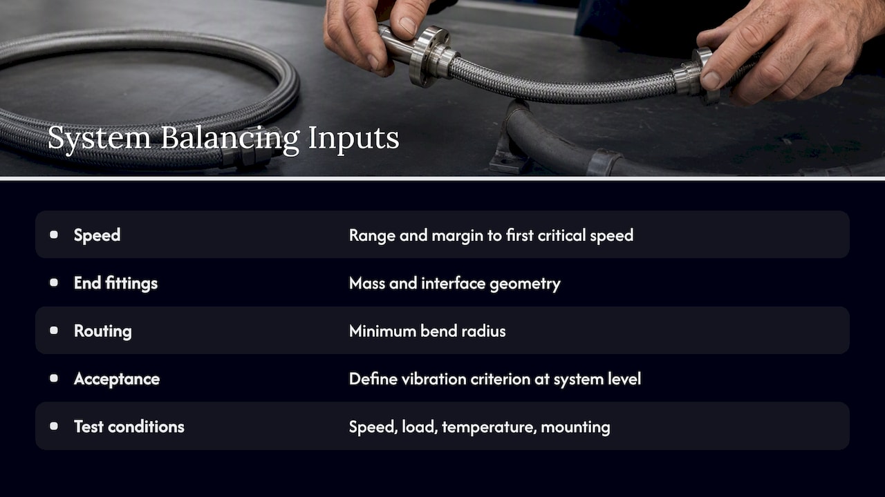
We therefore treat three inputs as the starting data for any drive that is expected to run at higher speed or in a confined installation: the speed range with the margin to the first critical speed, the mass and interface geometry of the end fittings, and the routing with its minimum bend radius. When these are known early, the need for later correction is reduced. When they are not known, the cause of a 1X vibration peak cannot be separated reliably from misalignment, looseness or a bent shaft.
For aerospace actuation and synchronization drives, we recommend defining the vibration acceptance criterion at system level and stating the test conditions: speed, load, temperature and mounting. The balance quality of single components is a means to that end.
— Uli
Custom drives and configurations
Where torque, speed, coupling interface and routing are specified, the shaft and its fittings can be configured to those inputs. BIAX manufactures actuation shafts and drive and tool shafts, and it supports one-off and small-batch requirements through special solutions and prototypes. Torque and speed requirements, coupling interfaces and shaft design are the typical parameters of such an inquiry.
FAQ
Does every flexible shaft need to be balanced?
Not necessarily. The decision depends on operating speed, length, construction and the proximity to critical speed. End fittings and couplings are commonly balanced as rigid components, while the installed shaft is judged by the vibration measured at the specified speed range.
What is the difference between static and dynamic balancing?
Static balancing corrects a displaced center of mass in one plane. Dynamic balancing addresses couple unbalance in addition and requires correction in two planes (Siemens). A flexible rotor near its critical speed may need multi-plane balancing.
Can balancing be done in the installed system?
Yes. In-situ balancing keeps the dynamic properties of the installed bearings and supports in the result, and DIN ISO 21940-13 describes the conditions, instrumentation and reporting. It is written for medium and large rotors, so applicability to a compact drive should be checked.
Which standard gives tolerances for flexible rotors?
ISO 21940-12 specifies procedures and tolerances for rotors with flexible behavior. It is guidance and allows deviations for specialized equipment, so the acceptance value is normally set by the application specification.
Contact
Technical questions on torque, speed, routing and interface requirements for a specific drive can be sent to BIAX through the contact options on the BIAX Flexwellen website.
Sources
- VDI 3839 Part 2: instructions on measuring and interpreting vibrations
- Fluke: diagnosing common vibration faults
- Fluke: dynamic unbalance
- Texas A&M Turbomachinery Laboratory: rotor balancing tutorial
- Texas A&M: rotating machinery rotor balancing
- Siemens: static, coupled and dynamic balancing
- ISO 21940-1:2019
- Hofmann: balancing and over-speed testing of flexible rotors
- DIN ISO 21940-13 (DIN Media)
- ISO 21940-12:2016-04 (DIN Media)
- ISO 21940-12:2016 (ISO)
- DIN ISO 21940-23 (DIN Media)
- BAuA: hand-arm vibration
- BAuA: machinery
Recommended
- Flexible shaft design for tight-space finishing applications
- Engineering standards for flexible shafts: a practical guide
- How to implement flexible shaft drive solutions (2026)
- Custom Flexible Shaft Configuration Guide for Engineers
Related Topics
Send your spec inquiry
Custom flexible shafts for your application — we quote within 1 working day.