Stop Overengineering Wellenenden: Shaft End Choices for Engineers
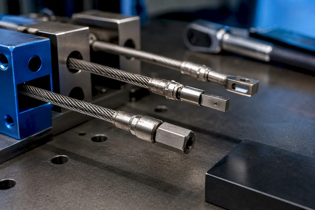
18 September 2026Wellenenden, the end fittings that terminate a flexible shaft and connect it to a motor, handpiece, or actuation link, determine how well torque transfers into a mechanism. For industrial finishing, crimped ferrules or hex flats handle repeated coupling cycles; for confined aerospace installs, pressed metal ends with positive-drive interfaces resist vibration; for RC drives, lightweight molded ends keep balance in check. The right choice always comes down to three constraints: torque, RPM, and bend radius. Suppliers provide both standard and custom-engineered ends designed according to torque, RPM, and bend radius requirements.
TL;DR:
- Tighter bend radii significantly decrease allowable torque, requiring oversized shaft cores to prevent friction buildup and slip during installation.
- High continuous RPM applications demand balanced and positively driven end fittings to avoid vibration, runout, and early failure.
- Custom shaft ends are often necessary when space constraints, harsh environments, or high duty cycles exceed standard product specifications.
- Proper installation practices, including correct coupling torque and adequate shaft extension, are critical for maintaining joint stability and system reliability.
- Regular inspection focusing on sheath integrity, runout, and coupling tightness can prevent unexpected failures and extend shaft service life.
Table of Contents
- What Types of Shaft Ends Are Available for Flexible Shafts?
- How Do You Choose the Right Shaft End for a Given Application?
- How Do Torque, RPM, and Bend Radius Interact in Shaft Design?
- Mounting and Coupling Options for Reliable Installation
- Maintenance, Inspection, and Troubleshooting for Shaft Ends
- An Engineering View on Shaft-End Selection
- Working With BIAX on Standard and Custom Shaft Ends
- Sources
- FAQ
What Types of Shaft Ends Are Available for Flexible Shafts?
Shaft ends fall into a handful of established geometries, each transmitting torque through a different mechanical principle. Crimped ferrules rely on radial compression around the shaft core, giving a permanent, vibration-resistant joint suited to high-cycle industrial use. Pressed or forged metal ends distribute load across a larger contact area and tend to outlast ferrules in continuous-duty applications. Square and hex flats create a positive drive interface that eliminates slip under sudden torque spikes, which matters more than friction fit once loads become unpredictable.
Threaded studs allow quick disassembly for maintenance but introduce a stress concentration point at the thread root that engineers should account for in fatigue calculations. Molded plastic ends reduce mass and cost for lighter-duty transmission, common in RC and consumer drive applications, though they trade off load capacity. Quick-release interfaces prioritize field serviceability over raw torque capacity, a fair trade in tool-change-heavy production lines.
Material choice for these ends follows the operating environment. Stainless steel (304 or 316) resists corrosion in washdown or marine-adjacent settings, plated carbon steel keeps cost down for dry indoor use, brass suits low-friction sliding fits, and engineering plastics handle low-load, weight-sensitive drives. End fittings and connectors are typically cataloged by connection type and size across these same material families which gives engineers a reference point when specifying a nonstandard geometry.
- Crimped ferrules: permanent, high-cycle, friction-and-compression fit
- Pressed/forged metal ends: broad contact area, continuous-duty rated
- Square/hex flats: positive drive, no slip under load spikes
- Threaded studs: field-serviceable, watch fatigue at the thread root
- Molded plastic ends: low mass, lower torque ceiling
- Quick-release interfaces: fast tool changes, moderate torque capacity
Pro Tip: Match end material to sheath material where corrosion is a risk. A stainless end on a stainless sheath avoids the galvanic couple that plated steel and stainless can form in humid or salt-exposed installations.
How Do You Choose the Right Shaft End for a Given Application?
Start with the two numbers that eliminate the most options fastest: required torque and RPM regime. A shaft end rated for intermittent torque will fail early under continuous load even if the peak numbers look identical on paper, so classify the duty cycle honestly before comparing candidates.
- Establish torque requirements. Record peak and continuous torque separately. A short, occasional torque spike (common in override or emergency-actuation systems) tolerates a different end design than sustained transmission in a grinding or polishing spindle.
- Define RPM range. Continuous high-speed operation raises questions about end mass and balance that intermittent low-speed use does not.
- Map bend radius and mounting geometry. The installation path, straight run, single bend, or serpentine routing around structure, sets a minimum radius that constrains which end styles and shaft diameters even fit.
- Assess environmental exposure. Temperature swings, moisture, chemical contact, and vibration all narrow the material shortlist.
- Set life-cycle expectations. A shaft end that gets disconnected weekly for maintenance needs different wear characteristics than one installed once and left alone for the equipment’s service life.
Before contacting a supplier, an engineer should have five figures on hand: maximum torque (peak and continuous), operating RPM, minimum bend radius in the installed path, expected duty cycles or service life, and the required coupling interface at both ends. Suppliers who receive incomplete specifications tend to propose over-engineered defaults, which adds cost and sometimes mass that the application doesn’t need. BIAX’s guidance on torque transmission best practices walks through how end design interacts with these numbers in more detail.
How Do Torque, RPM, and Bend Radius Interact in Shaft Design?
These three variables do not act independently. Tightening the bend radius increases internal friction between the shaft core windings, and that friction directly reduces the torque the shaft can transmit before slip or heat buildup becomes a problem. Manufacturer torque-versus-radius data shows this isn’t a gentle slope. Torque capacity can fall sharply once radius drops below a shaft’s rated minimum, which is why checking a supplier’s torque-vs-radius chart matters more than relying on a single “maximum torque” spec sheet number.
The practical implication: design for the largest bend radius the installation envelope allows, and when space forces a tight radius, upsize the shaft core rather than accepting reduced torque at the original diameter. This tradeoff shows up constantly in confined aerospace installs, where actuation runs snake around structural members and radius is dictated by the airframe, not the engineer’s preference.
RPM introduces a separate but related constraint. At higher continuous speeds, end mass and balance start to matter because an unbalanced end fitting generates runout and vibration that a slow-speed application would never reveal. Dedicated flex-shaft systems that run at higher continuous power typically require positive-drive end connectors and balanced end mass specifically to avoid this failure mode, a requirement that lighter attachment-style shafts rarely need to meet.
- Tighter bend radius → higher internal friction → lower allowable torque
- Higher continuous RPM → end mass and balance become critical
- Long unsupported runs at speed → whip and vibration risk rises
- Protective sheaths and intermediate guides reduce both friction losses and vibration on longer runs
Material selection closes the loop. Stainless cores and ends hold up under repeated flexing at elevated temperature better than plated carbon steel, but add cost and, in some grades, reduce fatigue life relative to alloy steel cores rated for the same torque. The load combination that most often triggers a custom shaft end, rather than a catalog part, is high continuous torque paired with a tight bend radius and a corrosive or high-temperature environment. That combination shows up repeatedly in thrust reverser actuation and valve override linkages, where space, heat, and duty cycle all push against each other simultaneously.
Mounting and Coupling Options for Reliable Installation
Coupling method affects torque repeatability as much as the end geometry itself. A set-screw-on-flat coupling is simple to install and service but depends on correct screw torque. Under-torque and the joint slips under load; over-torque and it can deform the shaft flat or strip the screw. Hex and square fits provide a positive mechanical lock that tolerates a wider range of installation torque, at the cost of needing a matched socket on the mating component. Threaded studs give the most repeatable reconnection but require axial space for a nut or matching thread on the driven side. Press-fit ferrules deliver the most compact, vibration-resistant joint but are effectively permanent once installed. Quick-release couplings trade some torque capacity for tool-free disassembly, which is the right call anywhere maintenance frequency outweighs raw load requirements.
Installation practice affects reliability as much as the coupling choice. A commonly cited rule of thumb calls for the inner shaft core to extend roughly 3/4 inch (about 19 mm) beyond the protective sheath for secure engagement in many handpiece and coupling systems. Too little extension leaves the joint unstable; too much increases friction and raises the risk of the exposed core whipping at speed. Alignment matters just as much: any coupling that introduces axial load on the shaft, rather than pure torque, shortens service life regardless of how well the end itself is made.
- Set-screw-on-flat: simple, torque-sensitive to install
- Hex/square fit: positive lock, tolerant of installation variance
- Threaded stud: highly repeatable, needs axial clearance
- Press-fit ferrule: compact and permanent
- Quick-release: fastest service, moderate torque ceiling
Longer runs, and any run with more than one bend, benefit from intermediate guides or a protective sheath sized to the application. Guides prevent the shaft from bowing under its own torque reaction and keep the bend radius within its rated minimum along the entire path, not just at the endpoints.
Maintenance, Inspection, and Troubleshooting for Shaft Ends
Reliable performance depends on a short, repeatable inspection routine rather than a reaction to failure. Follow this sequence during scheduled maintenance or whenever a shaft’s behavior changes:
- Visual inspection. Check the sheath for cracking, kinking, or discoloration, and check end fittings for deformation or corrosion at the joint.
- Runout check. Rotate the shaft slowly and watch for wobble at the end fitting, an early indicator of an unbalanced or loosening joint.
- Coupling torque check. Verify set screws and collets are at the manufacturer’s specified torque; a joint that has loosened even slightly will show up as intermittent slip before it fails outright.
- Sheath condition. Confirm the sheath still constrains the core through its full bend path, since a compromised sheath changes the effective bend radius under load.
Lubrication intervals and lubricant type should always follow the manufacturer’s specification for that particular shaft core, since core wire diameter and winding pattern change how the lubricant behaves under load. A shaft that starts running hot without a change in load usually points to insufficient lubrication or a bend radius that has effectively tightened due to a shifted guide.
When symptoms appear, work through them in order: slipping points to a loose or worn coupling first; vibration points to imbalance or a bent end fitting; heat buildup points to lubrication or an over-tight bend; and gradual torque loss usually traces back to core wear from repeated flexing near or below the rated minimum radius. BIAX’s maintenance guidance for engineers covers these checks in more detail for teams standardizing an inspection schedule across multiple installed units.
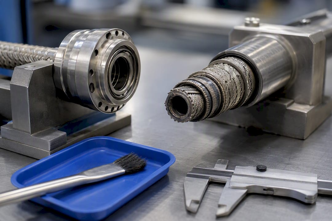
Pro Tip: Disconnect both ends before troubleshooting a suspected core problem. Checking coupling tightness with the shaft still under load makes it nearly impossible to distinguish a loose set screw from genuine core wear.
An Engineering View on Shaft-End Selection
Most selection guides treat torque, RPM, and bend radius as three separate checkboxes. They are not. A shaft end that passes a torque rating at full radius can fail well below its rated capacity once the installation forces a tighter bend, and that interaction is exactly where inexperienced specification goes wrong. The chart lookup is not optional homework. It is the calculation that actually determines whether an end survives its intended service life.
Aerospace applications sharpen this problem because the constraints rarely cooperate. Confined installs around thrust reverser mechanisms, flap and slat actuation linkages, and valve override systems demand tight bend radii precisely where torque and duty cycle are least forgiving. Certification requirements add another layer: a shaft end that is mechanically sound but undocumented for its service environment is not a usable part in a certified assembly.
Some suppliers work with design and procurement engineers to produce standard end geometries as well as custom configurations sized to a documented torque, RPM, and radius envelope rather than a generic catalog fit.
— Uli
Working With BIAX on Standard and Custom Shaft Ends
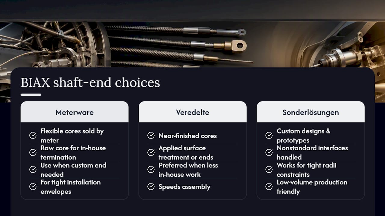
BIAX Flexwellen supplies both catalog shaft-end configurations and fully custom designs, so an engineer isn’t forced to accept a generic fit when the installation envelope has unusual constraints. Where a project needs raw core material for in-house end termination, the Biegsame Wellen Meterware line supplies flexible shaft cores by the meter. Where a near-finished component is preferred, the Veredelte biegsame Wellen line offers cores with applied surface treatment or end preparation already in place. For nonstandard interfaces, tight radius constraints, or low-volume production, the Sonderlösungen und Prototypen program covers custom design work down to prototype quantities.
Before requesting a quote, gather the same five figures the checklist above outlines: maximum torque (peak and continuous), operating RPM, minimum installed bend radius, expected duty cycles, and the coupling interface required at each end. Engineers weighing a fully custom geometry can review the custom flexible shaft design process for what that specification exchange looks like in practice, then reach the BIAX team through the contact page to start a technical review.
Sources
The Machine Design overview of flexible rotary shafts explains the torque-versus-bend-radius relationship in depth. Swagelok’s end-connection catalog documents standard connector types and materials. The flex-shaft system selection guide compares dedicated systems to attachments. A HELLA patent example illustrates a multi-output flexible shaft design in a confined headlamp adjustment mechanism.
- Flexible rotary shaft operation, uses and advances — Machine Design
- Flexible tubing — end connections — Swagelok
- Flex shaft rotary tool systems: selection, use, and maintenance — Build-Construct
FAQ
What Is a Wellenenden Flexwelle?
A Wellenenden Flexwelle refers to the end fitting on a flexible shaft, the component that connects the flexible core to a motor, handpiece, or driven mechanism. Common forms include crimped ferrules, hex or square flats, threaded studs, and molded ends, each suited to different torque and coupling requirements.
What Is the Minimum Bend Radius for a Flexible Shaft?
Minimum bend radius depends on shaft diameter, core construction, and rated torque, and manufacturers publish it as part of a torque-versus-radius chart rather than a single fixed number. Tightening the radius below that rated minimum reduces allowable torque and raises internal friction, so engineers should always check the specific chart for their shaft diameter before finalizing an installation path.
How Far Should the Shaft Core Extend Beyond the Sheath?
A commonly used rule of thumb calls for roughly 3/4 inch (about 19 mm) of inner core extension beyond the sheath for secure engagement in many handpiece and coupling systems. Too little extension causes instability at the joint, while too much raises friction and the risk of the exposed core whipping at speed.
Does BIAX Offer Custom Shaft End Configurations?
Yes. BIAX Flexwellen produces both standard shaft-end geometries and fully custom configurations engineered to a specified torque, RPM, and bend radius envelope, including low-volume and prototype runs. Pricing for custom work varies by specification; current details are available on the manufacturer’s site.
Why Does RPM Affect End Fitting Selection?
At higher continuous RPM, end mass and balance become critical because an unbalanced fitting generates runout and vibration that low-speed applications rarely encounter. Dedicated flex-shaft systems running at higher continuous power typically require positive-drive connectors and balanced end mass to prevent this.
Recommended
- Custom Shaft Configuration Advantages for Engineers
- Shaft Design Considerations for Engineers: A Technical Guide
- Proven tips for optimizing shaft design for industrial efficiency
- Custom Shaft Configurations Explained for Design Engineers
Related Topics
Send your spec inquiry
Custom flexible shafts for your application — we quote within 1 working day.


