Five Tests That Reveal Flexible Shaft Faults for Aerospace Engineers
7 September 2026Five tests reveal nearly everything about a flexible shaft’s condition: visual/dynamic inspection, runout measurement, non-destructive testing (ultrasound or borescope), accelerated torsional fatigue testing, and lubrication/temperature checks. Together, these methods detect surface damage, misalignment, internal defects, torsional weak points, and lubrication failure. Pull a shaft from service immediately if you find wind-spacing gaps, casing bulges, failing runout tolerances, or a temperature rise past your set threshold.
TL;DR:
- Accelerated torsional testing combined with non-destructive internal inspection detects design flaws and internal defects early during prototype development.
- Routine field inspections should focus on visual checks for wind-spacing gaps, casing bulges, and temperature rises exceeding established thresholds.
- Automated ultrasonic backscatter and borescope testing offer reliable identification of internal wire breaks and trapped debris in volume production.
- Setting pre-defined temperature and torsional deflection thresholds during testing allows quick identification of internal wear before failure.
- Proper fixture design, calibration, and detailed documentation are crucial to ensure repeatable, trustworthy results during inspection and testing.
Table of Contents
- What Is Prüfverfahren Flexible Welle? Test Categories and When to Use Them
- Runout, Wind-Spacing, and Coupling Inspection Procedures
- Non-Destructive Testing Methods for Internal Defects
- Accelerated Torsional Testing and Run-In Procedures
- Lubrication and Temperature as Wear Indicators
- Instrumentation and Fixture Design for Repeatable Results
- Acceptance Criteria and Documentation Standards
- BIAX Engineering Perspective: Testing Priorities for Aerospace-Critical Shafts
- Getting Test-Assisted Qualification Support From BIAX
- Sources
What Is Prüfverfahren Flexible Welle? Test Categories and When to Use Them
A structured prüfverfahren flexible welle (flexible shaft test procedure) sorts into four categories: static/visual inspection, dynamic inspection under motion, non-destructive testing (NDT), and accelerated fatigue testing. Each targets a different failure mode, and matching the method to the development stage saves both time and scrapped prototypes.
- Prototype qualification calls for accelerated torsional testing paired with NDT, since design flaws surface fastest under predetermined torsional load and angular offset conditions rather than years of field service.
- Production sampling relies on runout measurement and visual checks, run on a percentage of output or 100% of safety-critical batches.
- Field maintenance favors quick visual inspection and temperature monitoring, since these require no teardown and fit into routine service intervals.
Manual checks are cheap but inconsistent across operators. Automated NDT costs more upfront but produces the repeatable digital records that aerospace quality systems demand.
Runout, Wind-Spacing, and Coupling Inspection Procedures
Mechanical inspection starts with the shaft mounted in a test fixture, rotating under dual displacement sensors positioned at fixed intervals along the shaft length. The differential signal between the two probes flags out-of-roundness and bending that would otherwise show up later as vibration or premature wear.
- Mount the shaft between centers or in a rotating fixture that does not induce artificial bending.
- Rotate at a controlled speed while both displacement sensors record continuously.
- Compare the differential runout value against your tolerance band; flag any reading outside spec for rejection or rework.
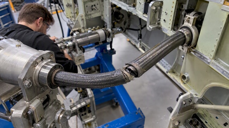
- Follow with a visual pass: check wind-spacing gaps between coil layers, look for casing bulges, kinks, abraded outer sheathing, and damaged coupling interfaces.
- Verify exposed shaft length, leader fit, and coupling bolt torque against the drawing.
Pro Tip: Run the visual checklist before the runout test, not after. A shaft with an obvious bulge or kink rarely needs instrumented confirmation, and skipping straight to visual triage saves fixture time on units you’re going to reject anyway.
Trim and remove a shaft from service the moment wind-spacing gaps widen beyond spec or a coupling interface shows visible wear at the bolt holes.
Non-Destructive Testing Methods for Internal Defects
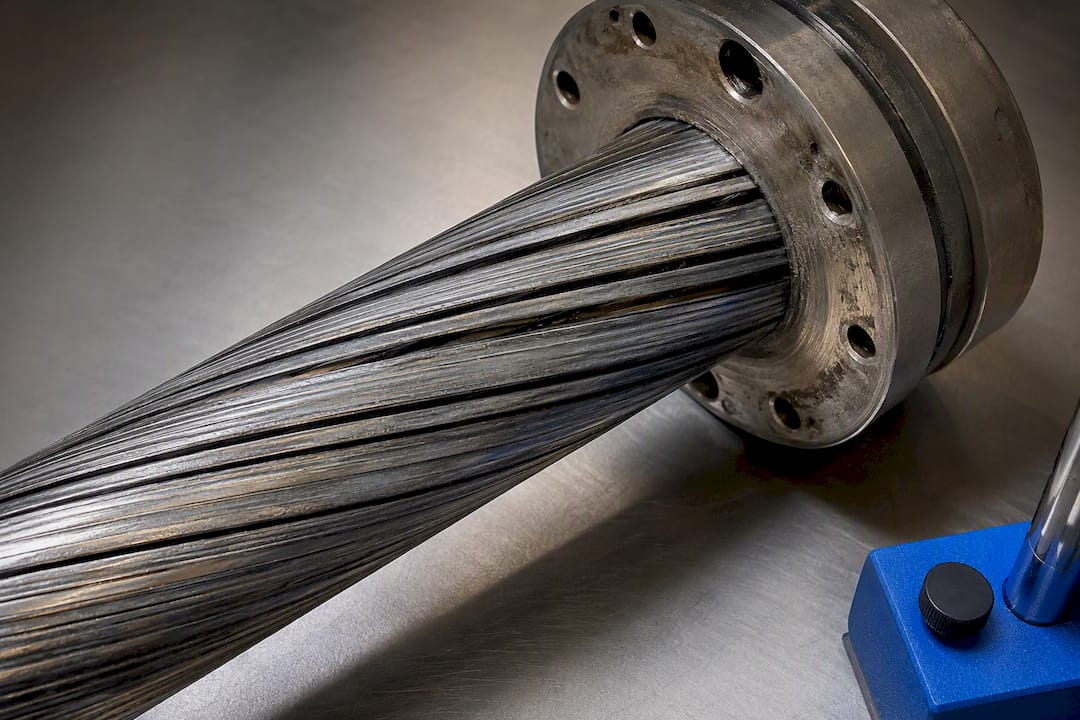
Surface inspection cannot see inside the shaft core, which is where wire breaks and retained debris usually start. Two NDT methods cover that gap: ultrasonic backscattering and borescope inspection.
Ultrasonic backscattering sends a sound pulse into the shaft material and reads the reflected energy pattern to detect subsurface defects without cutting the part open. Fraunhofer IZFP’s SHD backscatter systems demonstrate calibration-free measurement of depth-resolved features, and the same probe technology has migrated from hand-held units into fully automated inspection lines. Probe frequency and coupling medium both affect resolution, so match the probe to the wire diameter and core construction you’re testing rather than using a single frequency across every shaft variant.
Borescope inspection covers what ultrasound sometimes misses: internal wire breaks, trapped debris, and abrasion along the bore. It’s the right call whenever ultrasonic results are ambiguous or when a shaft has already shown symptoms like binding or unusual noise.
Automation pays off at volume. Automated NDT systems remove operator-to-operator variability and generate consistent digital records that integrate directly into asset-lifecycle management systems, which matters when a quality audit asks for traceable inspection history rather than a signed paper checklist.
- Ultrasonic backscatter: best for wire breaks and core delamination hidden below the surface.
- Borescope: best for confirming ambiguous ultrasonic readings or checking bore contamination.
- Automated lines: best when inspection volume justifies the fixed cost of probe calibration and data logging.
Accelerated Torsional Testing and Run-In Procedures
Full iron-bird testing on an assembled flight-control system is expensive and slow. Accelerated torsional testing gets you most of the same information on a bench, weeks earlier in the program.
- Set a predetermined torsional load and a fixed angular offset between the drive and driven ends, following the approach used to validate aerospace-grade flexible drive shafts without full-scale flight testing.
- Cycle the shaft through repeated torsional loading at that offset, tracking torque and angular deflection over time rather than running to a fixed cycle count and stopping.
- Add a directional run-in step: briefly rotate the shaft in one direction before full-load testing to let it settle to resting length and reveal binding or kinking introduced during winding or handling.
- Watch for two failure signatures: gradual angular deflection drift, which usually points to core wear, and sudden torque decay, which usually points to a wire break or coupling slip.
Subsystem-level accelerated testing during prototype qualification catches design deficiencies earlier than waiting for full assembly testing, which shortens the feedback loop between a design change and knowing whether it actually fixed the problem. For engineers building test rigs from scratch, understanding the underlying torsion and torque relationships makes it easier to set realistic load and offset targets.
Lubrication and Temperature as Wear Indicators
Temperature is the cheapest, least invasive wear indicator available for a flexible shaft, because internal friction shows up as heat well before it shows up as measurable torque loss.
Lubrication choice drives that temperature curve directly. Testing that compared lubrication methods found that dry film lubricant (DFL) applied through the shaft core, combined with grease, produced lower running temperatures and lower torsional deflection than surface-only lubrication or no lubrication at all. The through-shaft application matters because surface grease alone doesn’t reach the wire-to-wire friction points inside the core.
- Measure temperature near the bearing housings and again at mid-span; a gap between the two locations often points to a localized wear zone rather than general aging.
- During endurance runs, log temperature at fixed intervals rather than spot-checking, so a slow drift doesn’t get missed between readings.
- Pair a rising temperature trend with torsional deflection data. When both climb together, that’s a stronger internal-friction signal than either reading alone.
Set an action threshold before testing starts, not after you see a suspicious number. Shafts running above your baseline temperature by a fixed margin should be pulled for inspection regardless of how many cycles remain in the plan. Engineers specifying shafts for high-speed applications should also review lubrication guidance for shafts above 10,000 rpm, where thermal margins run tighter.
Instrumentation and Fixture Design for Repeatable Results
Test data is only as good as the fixture holding the shaft. A rig that induces its own bending will corrupt runout and torsional readings before the shaft ever sees a real defect.
Recommended instrumentation includes displacement probes or LVDTs for runout, torque transducers for the accelerated torsion test, thermocouples or infrared sensors for temperature monitoring, and ultrasonic probes or borescopes for internal defect checks. Chucks and bearing supports need to hold the shaft on its natural centerline rather than forcing it into a fixed geometry that doesn’t match its installed configuration.
- Use alignment jigs to keep drive and driven ends coaxial before applying any angular offset.
- Log sampling rates high enough to catch transient torque spikes, not just steady-state averages.
- Perform a master-wave calibration check on ultrasonic equipment before each test batch to help ensure probe consistency.
Pro Tip: Keep one “reference” shaft with known, documented defects on hand purely for calibration runs. It’s the fastest way to confirm your ultrasonic setup and displacement sensors are reading correctly before you trust the day’s production data. Engineers building test protocols from scratch may also find the shaft design checklist useful for cross-checking fixture assumptions against original design intent.
Acceptance Criteria and Documentation Standards
Numeric acceptance criteria need to be specific enough to act on, not just “no visible damage.” The ranges below are starting points to adapt to your own shaft diameter, core construction, and application load.
| Parameter | Example acceptance range | Basis |
|---|---|---|
| Runout | Within manufacturer tolerance band for shaft diameter | Dual-sensor differential measurement |
| Temperature rise over baseline | Flag above a fixed margin set during design validation | Continuous monitoring during endurance run |
| Torsional deflection | Flag any measurable upward drift versus initial baseline | Accelerated torsion test data |
Set inspection intervals from fracture-mechanics principles and test-derived crack-growth data rather than relying only on a historical record of no failures, since a shaft with zero prior cracks can still be closer to critical crack length than one with a documented, stable defect.
- Fixture and sensor IDs used for the test run
- Calibration records and master-wave reference data
- Raw data snapshot alongside the pass/fail summary
- Recommended corrective action for any rejected unit
BIAX Engineering Perspective: Testing Priorities for Aerospace-Critical Shafts
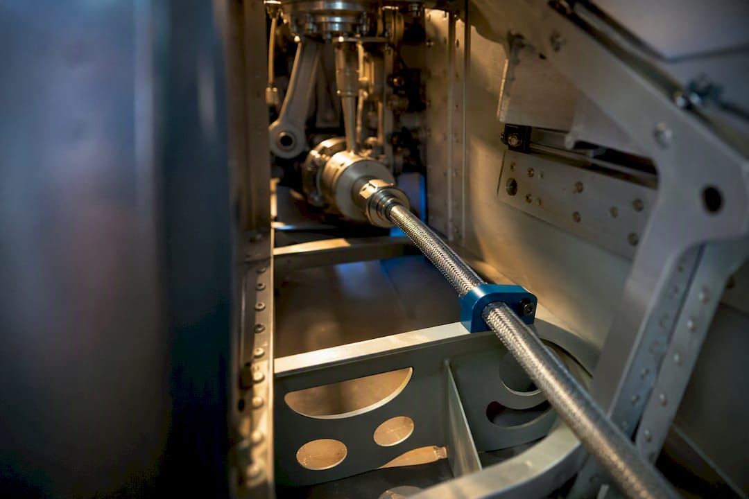
Biax-flexwellen provides engineering support for torque, RPM, and coupling interface requirements on flexible shaft installations, including the confined and hard-to-reach configurations common in thrust reverser systems, flap and slat actuation, as well as synchronization shaft arrangements.
For these installations, accelerated torsional testing and automated ultrasonic NDT earn priority over other methods, because both catch design and material weaknesses before a shaft is buried inside a mechanism that’s expensive to disassemble for inspection. A runout failure on a bench is a quick rework. A runout failure discovered after installation in a valve override system inside a nacelle is a very different problem.
— Uli
Getting Test-Assisted Qualification Support From BIAX
Vendor-assisted qualification makes sense once a project moves past generic bench testing into aerospace-grade acceptance work, tight installation envelopes, or a coupling interface that doesn’t match anything off a standard catalog page. Complex qualification programs benefit from engineering input at the design stage rather than after a test failure forces a redesign.
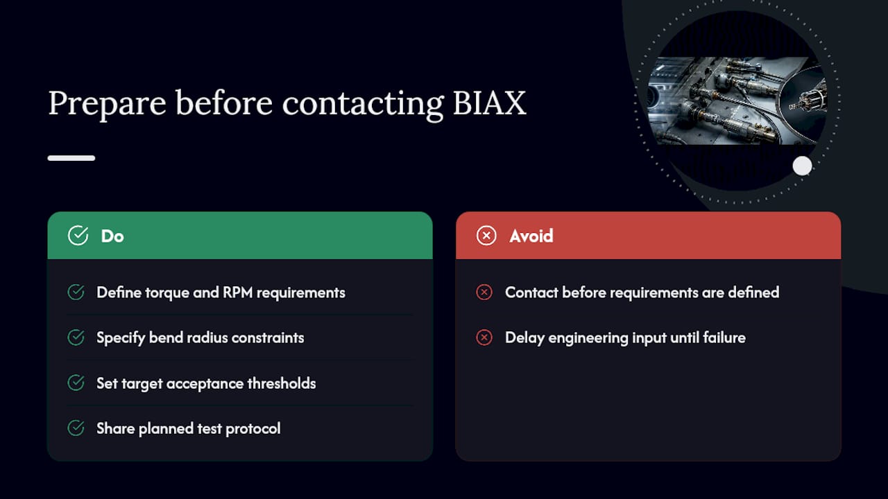
Before reaching out, have your torque and RPM requirements defined, along with bend radius constraints, target acceptance thresholds, and whatever test protocol you’re already planning to run. That information lets an engineering team give you a useful answer on the first exchange instead of a round of clarifying questions.
Engineering support includes standard components and custom-configured shafts designed around specific torque, RPM, and coupling requirements. If your application involves a confined installation or a coupling interface that needs custom engineering, review the custom flexible shaft design process or explore flexible shaft applications for industrial manufacturing to see configuration options relevant to your test program. For direct engineering questions about a specific installation, reach the team through the BIAX contact page.
Sources
- Flexible shafts in aerospace applications | ElectronicsSpecifier
- Optimized requirements and verification for flexible drive shafts | SAE paper (2019)
- Prüfung auf Rundheit – an einem Elektromotor | burster
Recommended
- 7 Expert Flexible Shaft Maintenance Tips for Engineers
- How to Select Flexible Shafts for Precision Machinery
- Shaft Design Considerations for Engineers: A Technical Guide
- Custom Flexible Shaft Configuration Guide for Engineers
Related Topics
Send your spec inquiry
Custom flexible shafts for your application — we quote within 1 working day.