Flexible Shafts at Large Bend Angles: Limits and Routing
16 November 2026A flexible shaft does not have a bend angle limit in the way a universal joint has a maximum articulation angle. The limit is the bend radius. A shaft can follow a path that changes direction by up to roughly 180°, as long as every point along the path stays above the minimum bend radius for that shaft diameter and the torque and speed are derated for the curvature. Angular accuracy depends on torsional windup, which grows as the shaft is bent more tightly. This article sets out the limits, the figures behind them and the routing checks for installations with a large angular offset, such as actuation and synchronization drives in confined airframe and industrial structures.
TL;DR
- The limiting parameter is the minimum bend radius, not the total change of direction. Paths of about 180° are possible when the radius is respected (Machine Design, 2006).
- Torque capacity falls as the radius shrinks. At the minimum radius, one source gives 20 % of nominal torque and a speed cap of 80 % of rated speed.
- Tighter bends raise internal friction between the wire layers, which means heat, wear and more torsional windup. Angular fidelity under load must be checked for the bent state, not the straight one.
- Specify the shaft with the bend radius, bend direction, torque, speed and duty cycle together. Parameters cannot all be optimized at once.
Table of Contents
- What a large bend angle means for a flexible shaft
- How the bend radius limits torque and speed
- Why tight bends cost efficiency: internal friction
- Angular fidelity: what bend angle does to rotation accuracy
- The design trade-off: not every parameter can be optimized
- Routing in confined installations
- Duty cycle changes the answer
- Specification checklist
- Our approach to large-offset installations
- FAQ
- Sources
What a large bend angle means for a flexible shaft
Three terms are often mixed up in this context.
Bend angle is the total change of direction between the drive end and the driven end. A shaft running from a motor, around a structural member, to an actuator may turn through 90°, 135° or more.
Bend radius is the radius of curvature of the shaft axis at any point along that path. A large bend angle can be made with a generous radius over a long length, or with a tight radius over a short length. These are very different loads on the shaft, although the angle is identical.
Angular offset (Winkelversatz) is the misalignment between the axes of the drive and the driven component. A rigid coupling or a universal joint has to absorb this offset at a defined point. A flexible shaft distributes it along its length, so that the offset is converted into a bend radius.
This is why the question “how large an angle can the shaft take” is better written as “what radius does the path require, over what length, and what does the shaft transmit at that radius”. Machine Design describes the bend radius, and not the absolute angular error, as the limiting factor for flexible shafts, with some shafts working through direction changes of about 180°.
How the bend radius limits torque and speed
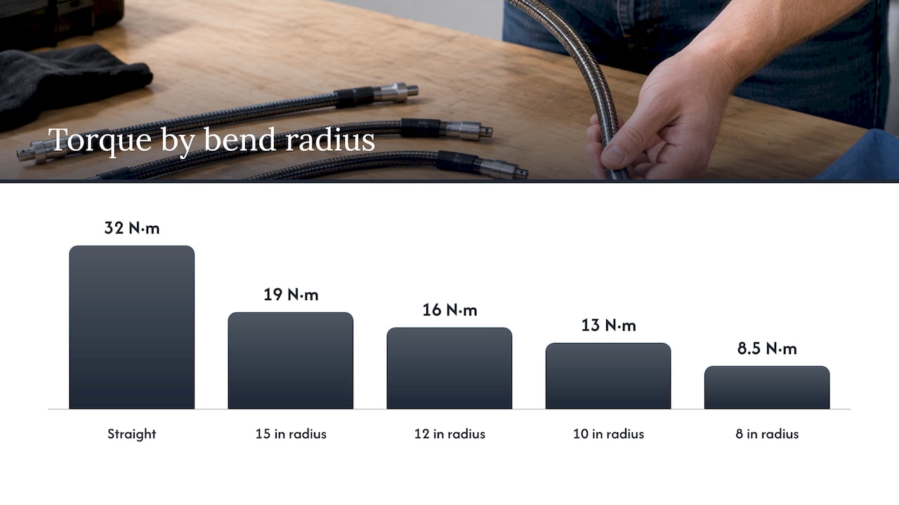
The published figures show how steeply capacity falls with curvature. For a 0.5-inch (about 12.7 mm) flexible shaft, Machine Design (2006) lists torque capacity against bend radius:
| Bend radius | Torque capacity (0.5 in. shaft) | Approx. in N·m |
|---|---|---|
| Straight | 284 lb-in. | 32 |
| 15 in. | 172 lb-in. | 19 |
| 12 in. | 145 lb-in. | 16 |
| 10 in. | 117 lb-in. | 13 |
| 8 in. | 75 lb-in. | 8.5 |
The same source states that at the minimum bend radius the torque capacity drops to 20 % of the nominal value, that torque in the unwinding direction is about 30 % lower, and that speed at the minimum radius should not exceed 80 % of the rated speed. The N·m values above are our conversion of the published lb-in. figures.
The table shows two practical points. First, the loss is not linear: moving from a 15 in. radius to an 8 in. radius removes more than half of the available torque. Second, the direction of rotation relative to the lay of the outer wire layer matters. When the load tends to unwind the outer layer, capacity is lower again.
Minimum radius by shaft diameter
Broder and Boehm (2013) give minimum bend radii by shaft diameter:
| Shaft diameter | Minimum bend radius |
|---|---|
| 3 mm | 80 mm |
| 5 mm | 150 mm |
| 7 mm | 210 mm |
| 10 mm | 300 mm |
| 15 mm | 450 mm |
The ratio is roughly 27 to 30 times the diameter across this range. These are reference values from one publication. A given product has its own minimum radius, which depends on the core construction, the number of wire layers and the casing, and that value governs the design.
The same authors note that below the minimum radius the shaft can be permanently deformed, and that operation at the minimum radius transmits only about 30 % of the power, with the remainder lost as frictional heat. The two sources therefore quantify the penalty differently, 20 % of nominal torque in one case and 30 % of power in the other. This is expected: the figures describe different shaft constructions and different quantities. For a design, neither is a substitute for the data of the shaft actually selected.
Why tight bends cost efficiency: internal friction
A flexible shaft core consists of several wire layers wound in alternating directions. When the shaft bends, these layers press against each other. Parlato (2013) explains that the layers exert forces on each other during bending and generate friction, and that this internal friction increases as the bend radius decreases. Each flexible shaft therefore has a minimum operating radius below which it does not function correctly.
This friction produces three effects that matter in a design review:
- Heat. The lost power becomes heat in the core and the casing. In a closed or insulated bay with no airflow, the heat has nowhere to go, and lubricant temperature limits become relevant.
- Wear. Wire-to-wire sliding under load is the main wear mechanism. A shaft that runs continuously at its minimum radius will wear faster than one that sees the same radius only briefly.
- Windup. Higher friction and a more compliant bent core increase the angle by which the output lags the input under load.
Angular fidelity: what bend angle does to rotation accuracy
For a drive that must hold position or phase, the relevant question is whether the output angle follows the input angle. Two effects apply.
Speed uniformity. A flexible shaft has no discrete joint. A single universal joint at an angle produces a cyclic variation in output speed, and the variation grows with the joint angle. Compensating it needs a second joint at the correct phase and equal angle. A flexible shaft avoids this by design, because the bend is distributed along the core. This is one reason flexible shafts are considered where a path with several changes of direction is needed.
Torsional windup. The shaft behaves as a torsion spring. The twist under load depends on the core construction, the length and the bend. Broder and Boehm state that reducing the minimum radius increases twist, which is a disadvantage in remote-control applications. A shaft intended to be very flexible will therefore be less accurate in angular terms under load than a stiffer one.
For an engineer this leads to a practical rule: define the permissible angular error at the output for the maximum load and the tightest bend in service, then check the windup at that condition. A figure measured on a straight shaft at no load says little about it.
For position-critical actuation, such as a drive that is expected to set a surface or a valve to a defined position, windup can be limited in three ways: shorten the shaft, enlarge the bend radius, or choose a construction with higher torsional stiffness. Each has a cost in packaging space or flexibility.
The design trade-off: not every parameter can be optimized
Broder and Boehm point out that not all parameters can be optimized at the same time. A core designed for more torque has a larger minimum radius and so less flexibility. A core designed for a small minimum radius twists more. Their example of a high-power rating, 5 kW at 2,000 rpm for a 15 mm shaft, applies to nearly straight conditions.
The design sequence that follows from this is:
- Fix the route first, from the packaging space and the clearance to adjacent structure.
- Derive the tightest radius the route requires.
- Choose the diameter and construction whose minimum radius is below that, with margin.
- Check torque and speed at that radius, not at the straight rating.
- Check windup and the heat load for the duty cycle.
If step 3 and step 4 cannot be satisfied together, the route has to change, or the drive has to be split into two shorter shafts with an intermediate bearing or gearbox. Our guide to length selection, routing, bend radius and load goes through the length-related checks in more detail.
Routing in confined installations
Actuation and synchronization drives in airframes, and many industrial machines, share a set of constraints: little space, adjacent structure that moves or vibrates, and a requirement for predictable behavior over a long period. The following points apply to the routing of a flexible shaft in such an installation. They are general design considerations. Any qualification for a specific certified system is the responsibility of the system designer and the applicable standards.
Typical drive tasks
- Flap and slat actuation. A central drive moves several actuation points along a surface. The shaft transmits torque over a distance, around structure, and the synchronization of the end points depends on low and repeatable windup.
- Thrust reverser systems. Synchronized actuators are coordinated by a shaft path inside a confined nacelle environment, with temperature and vibration loads.
- Valve override systems. A manual or remote input must reach a valve that sits behind other components. The shaft carries a low torque but must work reliably from a defined position after long periods without use.
- Synchronization shafts. Two or more actuators are connected so that they move together. Equal windup in each branch is the design target.
The actuation shafts in our range are intended for this kind of remote actuation task: see Betätigungswellen.
Routing rules for large angular offsets
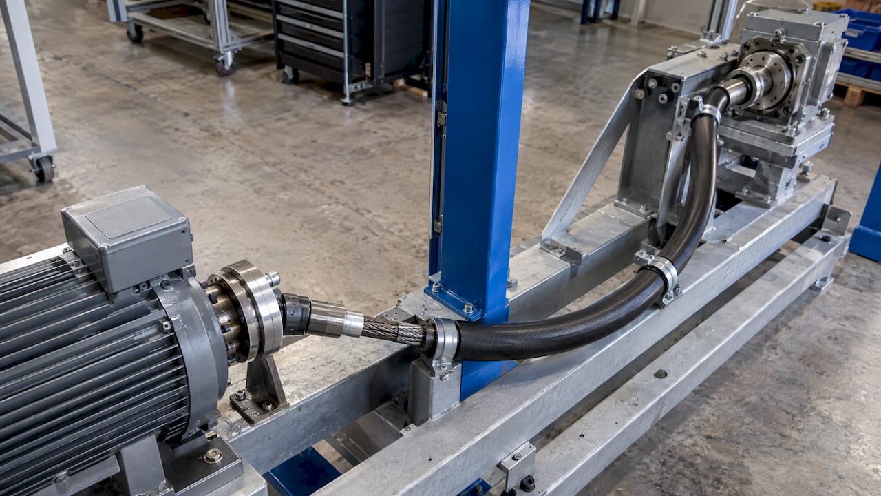
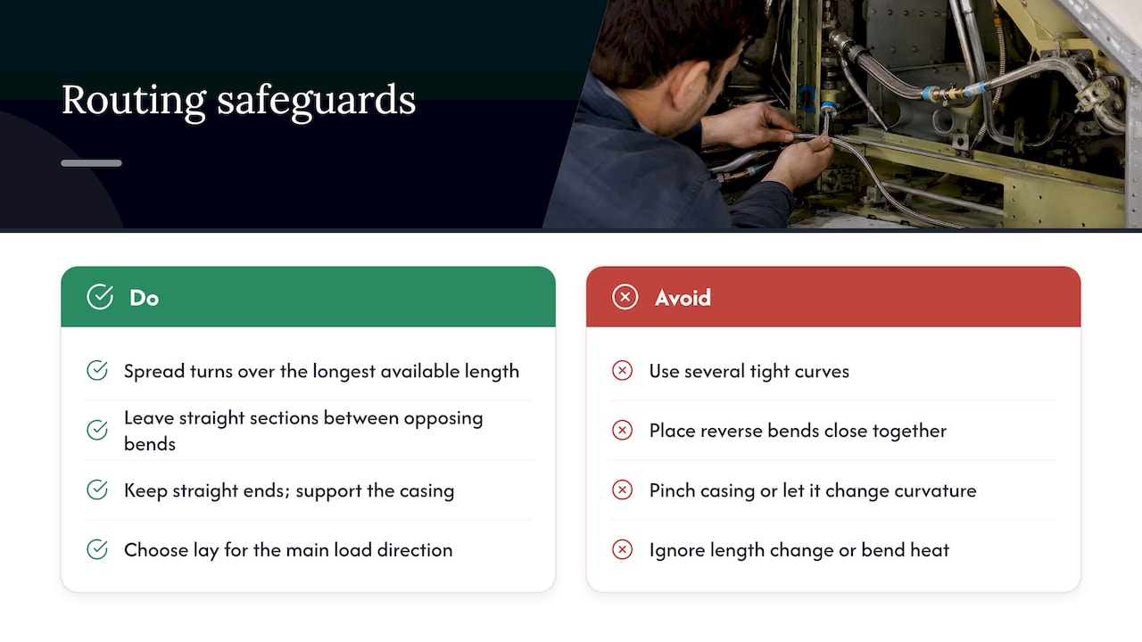
Use one smooth curve rather than several tight ones. Spread a 90° or 180° change of direction over the longest available length. A larger radius over a longer arc stresses the shaft less than the same angle in a short, tight arc.
Avoid reverse bends close together. An S-shaped route forces the wire layers to change their loading direction within a short length. Leave straight sections between opposing bends.
Keep the first and last sections straight. Near the end fittings, a bend puts the load on the transition between the flexible core and the rigid termination. A straight section at each end reduces the bending stress where the shaft is fixed.
Support the casing. The casing holds the radius. Clamps must fix its position without creating a local tight bend or pinching it. The shaft in a casing should not be allowed to change its curvature with machine vibration.
Account for the direction of rotation. Because capacity in the unwinding direction is lower, a drive that is loaded mainly in one direction should be specified with the lay chosen for that direction.
Allow for length change. Bending and loading change the effective length of the core relative to the casing. End fittings need axial freedom or tolerance for it.
Plan the thermal condition. Check the ambient temperature of the route and the heat generated at the bend. Where ambient temperature is high and the radius is near the minimum, the margin on lubricant and casing materials shrinks.
Assessing a route with a large offset
For each candidate route, record these values and compare:
| Parameter | What to determine |
|---|---|
| Total direction change | Sum of all bends, in degrees |
| Tightest radius | Smallest local radius on the route, in mm |
| Free length | Length between fixed supports |
| Torque at the tightest radius | From shaft data, not the straight rating |
| Speed at the tightest radius | Check against the speed cap for the bent state |
| Windup at maximum load | Output lag in degrees, for the longest branch |
| Duty cycle | Continuous, intermittent or rare actuation |
| Environment | Temperature range, vibration, contamination |
The torque transmission fundamentals and best practices on our site describe how the core transmits load, which helps when interpreting the shaft data in this table.
Duty cycle changes the answer
The same route can be acceptable for a drive that operates a few times per flight or per shift and not acceptable for a continuous drive. Heat builds up only in continuous running. Intermittent actuation at high torque, with long rest periods, allows tighter radii than a drive that runs for hours at the same bend.
For continuous finishing drives, such as a flexible shaft powering a deburring or polishing tool, the bend usually changes as the operator moves the tool, and the average radius is larger than the worst case. The worst case still has to stay above the minimum radius. For tool drives see the tool holder specifications and the guide to flexible shaft design for tight-space finishing.
Specification checklist
When requesting or defining a flexible shaft for a route with a large bend angle, include:
- Required torque and speed, with the operating point at the tightest bend, not only the straight-line rating
- The route as a drawing or 3D path, with minimum radius and total angle
- Direction of rotation, and whether the load reverses
- Permissible windup or angular error at the output
- Duty cycle and operating time
- Temperature range and exposure to fluids or contamination
- Required service life or number of cycles
- Interface geometry at both ends and the freedom of the end fittings
A complete set of these values lets the shaft be sized to the real condition. Without them, the shaft is sized to the straight rating and the route is found out during testing.
Our approach to large-offset installations
BIAX Flexwellen (Schmid & Wezel GmbH) produces standard and customized flexible shafts, including actuation shafts and special solutions in prototype and small-batch quantities, and is certified to ISO 9001. For routes with a large angular offset, we start from the route and the load case. The installation space defines the radius, and the shaft is configured to it, including core design, protective sheath, and end fittings. Standard components are available as metered flexible shaft cores and as refined flexible shafts. Where the route or the load case is outside the standard range, special solutions and prototypes are the path.
Our view on bend angle
The bend angle on a drawing tells us little. The radius, the length and the load at that radius tell us whether a flexible shaft will work. We ask for the route first, because the same 90° can be a comfortable path or a shaft at its limit.
In our experience as a manufacturer of flexible shafts, the strongest results come when the shaft is considered at the start of the layout and not after the surrounding structure is fixed. A custom configuration of core, sheath and end fittings can then be matched to the real torque, speed and bend conditions. That is the reason we produce both standard shafts and custom designs, down to single prototypes.
Windup, heat and minimum radius are connected. Treating them together in one specification avoids the redesigns that come from checking each in isolation.
Uli
FAQ
What is the maximum bend angle of a flexible shaft?
There is no fixed maximum angle. Flexible shafts can follow direction changes of up to about 180° according to Machine Design. What limits the design is the minimum bend radius, which depends on the shaft diameter and construction, and the torque and speed available at that radius.
How does angular offset between drive and driven axis affect a flexible shaft?
The offset is absorbed as a bend along the shaft. A larger offset over a short length means a smaller radius, which reduces torque capacity and raises internal friction. A longer shaft allows the same offset at a larger radius, with a lower load on the core.
Does a flexible shaft transmit rotation with angular accuracy at a large bend?
It transmits rotation without the cyclic speed variation of a single universal joint, but it twists under load. According to Broder and Boehm, a lower minimum radius increases the twist. Define the permissible output error at maximum load and the tightest bend, and check the windup at that condition.
What happens if the shaft is bent below the minimum radius?
The shaft can deform permanently, and internal friction rises sharply. Parlato notes that each flexible shaft has a minimum operating radius below which it does not work correctly. The route must be changed or a smaller-diameter or more flexible construction chosen.
What information is needed to specify a shaft for a large-offset route?
The route with minimum radius and total angle, torque and speed at the tightest bend, direction of rotation, permissible windup, duty cycle, environment and end interfaces. With these values, engineering can propose a configuration. Technical inquiries can be sent through BIAX Flexwellen, where the contact form is available.
Sources
- Taking torque around corners, Machine Design (2006)
- Flexible Options with Flexible Shafts, Broder and Boehm (2013)
- Flexible rotary shaft operation, uses, and advances, Machine Design (2013)
Recommended
- Flexible Shaft Length Selection: Routing, Bend Radius and Load
- Flexible Shafts for Tight Spaces: Boosting Precision
- Flexible shaft design for tight-space finishing applications
- Flexible Shafts Maintain 85-95% Efficiency in Tight Spaces
Related Topics
Send your spec inquiry
Custom flexible shafts for your application — we quote within 1 working day.