Flexible Shaft Heating: Causes, Limits and Troubleshooting
30 October 2026A flexible shaft heats up because part of the input power is lost as friction between the rotating core and the stationary casing. Heat rises with tighter bends, higher speed, higher load, poor lubrication and long continuous duty. A moderate, stable temperature plateau is normal. A steadily climbing temperature, or a sudden step after start-up, points to a fault or to operation outside the shaft’s specification. This article explains the mechanisms, the operating conditions that drive them, a method to judge a measured temperature, and the points to check in aerospace and industrial installations.
TL;DR
- Heating in a flexible shaft is friction loss: core wires against each other, and core against casing. It increases with bend severity, speed and torque.
- A stable plateau after warm-up is expected. A continuing rise, a rapid jump after start-up or a local hot spot is the signal to investigate.
- The main causes in service are bend radii below the specified minimum, dry or degraded grease, misalignment at the end fittings, overload and excessive duty cycle.
- Measure surface temperature at defined points, compare it with ambient and with a recorded baseline, and stop operation when limits from the manufacturer’s data sheet are approached.
- Shaft length, routing and lubrication should be fixed at the design stage, together with torque, speed and temperature range.
Table of Contents
- How a flexible shaft transmits torque, and where the heat comes from
- Operating conditions that drive heating
- Aerospace installations: confined spaces and mixed requirements
- Is the temperature rise normal or a fault?
- Troubleshooting heating step by step
- Reducing heating at the design stage
- Industrial finishing: the same mechanism, a different duty
- Perspective: specify the thermal case with the shaft
- Specifying a shaft for a defined thermal case
- FAQ
- Contact
- Sources
How a flexible shaft transmits torque, and where the heat comes from
A flexible shaft consists of a core made of several layers of wire wound helically in alternating directions. The core rotates inside a protective sheath or casing made of metal or plastic, and it is lubricated with grease (Wikipedia, Welle (Maschinenelement)). The alternating winding directions allow the shaft to carry torque in one rotation direction with high stiffness while remaining bendable.
Three friction zones produce heat:
- Wire-to-wire friction inside the core. Each layer slides against its neighbors as the core bends and twists under load. The sliding increases with torque and with bend angle.
- Core-to-casing friction. The outer layer of the core presses against the casing wall, particularly on the outside of a bend. A layer of lubricating grease between core and casing reduces friction and wear (TU Hamburg, academic work on flexible shafts).
- End-fitting and bearing friction. Misaligned couplings, worn bearings and seals add load that appears as heat near the connection points.
A patent description for high-speed flexible shafts states the mechanism plainly: in high-speed applications the shaft becomes hot from constant friction of the shaft wires, and routing along a tight radius adds friction against the casing, which shortens shaft life (US patent 4,424,045). The same document lists aircraft engine scavenger pump drives among the typical uses of such shafts.
An industry article on flexible shaft selection reports that under minimum bending conditions only 30 percent of the power is transmitted, the rest being friction loss radiated as heat (Flexible Options with Flexible Shafts). The figure applies to the extreme case. In a gently routed shaft the loss is far lower, which is why routing is the first design variable to review. BIAX publishes a discussion of efficiency in tight spaces that covers the efficiency range for typical installations.
Operating conditions that drive heating
Four variables dominate. They interact, so none should be assessed alone.
Bend radius and total bend angle
Friction between core and casing grows with the contact force on the outside of the bend. A smaller radius raises this force. Every flexible shaft type has a minimum bend radius in its data sheet. Operating below it increases heat, accelerates wear and can raise the risk of core fatigue. Total bend angle matters as well: three moderate bends add up to more contact length than one. Routing guidance is covered in the article on length selection, routing, bend radius and load.
Speed
Frictional power loss rises with rotational speed because the sliding velocity between wires and between core and casing rises with it. At speeds above 10,000 rpm, grease selection, fill quantity and grease aging become decisive. The lubrication requirements for that range are described in a separate guide to flexible shaft lubrication above 10,000 rpm. Shafts specified for tool drives can reach speeds up to 50,000 rpm, as in the drive and tool shaft range, and at that level heat management is part of the specification, not a service topic.
Torque and load profile
Heat scales with transmitted torque. A shaft that is continuously loaded near its rated torque will settle at a higher temperature than one loaded at 50 percent. Torque peaks are a separate concern: a stall or jam in the driven mechanism produces a sudden torque spike, which twists the core, compresses its layers and generates heat within seconds.
Actuation shafts, as used for synchronization or manual override, usually see low speed and intermittent torque. For them, heating is less a steady-state issue and more a question of end-stop loads, binding and low-temperature grease stiffness.
Duty cycle and ambient temperature
Intermittent duty lets the shaft cool between cycles. Continuous duty does not. The ambient temperature sets the starting point: a shaft that settles 30 K above ambient reaches a very different absolute temperature in a cold-soaked airframe than next to an engine nacelle. Limits for grease, plastic sheaths and any end seals must be checked against the absolute temperature, not the rise alone. The temperature range specification guide lists the points to define.
| Condition | Effect on heating | Design response |
|---|---|---|
| Bend radius below specified minimum | Higher core-casing contact force and friction | Reroute, increase radius, shorten total bend angle |
| High speed | Higher sliding velocity, more friction power | Select grease for speed, check fill, consider shaft diameter |
| Torque near rating or peaks | More wire-to-wire friction, core twist | Size shaft with margin, add torque limiting |
| Continuous duty | No cooling intervals | Define duty cycle, verify steady-state temperature |
| High ambient temperature | Higher absolute temperature | Check grease and sheath limits at the real ambient |
| Misalignment at end fittings | Local friction and side load | Align couplings, support the casing near the ends |
Aerospace installations: confined spaces and mixed requirements
Aerospace applications put several of these conditions together. Flexible shafts appear in synchronization of actuators, in flap and slat drive systems, in valve override mechanisms and in thrust reverser systems. In a thrust reverser, for example, a flexible synchronization shaft in a conduit connects the actuators so that they extend and retract at the same time and rate, as described in a patent on a synchronization shaft lock.
Typical design constraints in these installations:
- Confined routing. Available space often forces bends close to the minimum radius. Heating margin is then small, and routing should be verified on the real structure, not only in CAD.
- Wide temperature span. The shaft may see cold-soak conditions and, near engines, elevated temperatures. Grease must stay functional across the full span, and the stiffening of grease at low temperature can raise drive torque at start-up.
- Low speed, long life. Synchronization and actuation shafts rotate slowly but must run for many cycles. Wear and fatigue are then a bigger concern than steady heating, though friction heat still shortens grease life.
- Vibration. Engine and airframe vibration adds cyclic loading to the casing and the end fittings.
Qualification of a shaft for any aircraft system follows the requirements of the aircraft manufacturer and the certifying authority. Heating limits for such a system come from the system specification, not from general rules.
Is the temperature rise normal or a fault?
No single temperature value separates normal from faulty. The assessment rests on comparison.
Establish a baseline
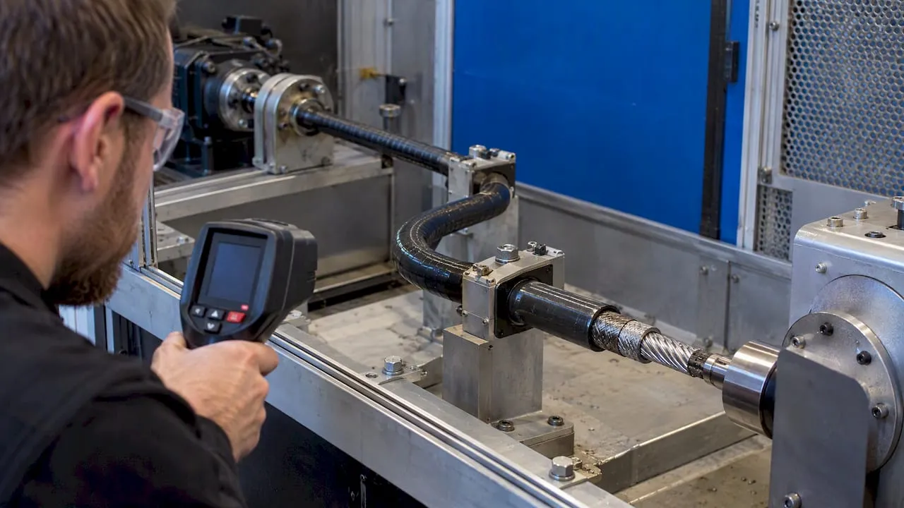
Mechanical systems produce thermal energy in normal operation, and a thermographer must know the normal thermal signature of a component to tell a developing fault from regular behavior (Peterson, infrared thermography of mechanical systems). For a flexible shaft this means recording surface temperature of the casing at defined points (both ends, the tightest bend, a straight section) on a known-good assembly, under known speed, torque and ambient temperature.
Compare with ambient and track the profile
A rise can be assessed by tracking its profile, comparing it with the normal thermal pattern and ambient temperature, and noting rapid increases after start-up. Heat can indicate friction, lubrication problems or overload (ICS Schneider, temperature problems in machines). Comparing the component’s surface temperature with ambient helps separate environmental or cooling issues from heat produced by the component itself or its operating conditions.
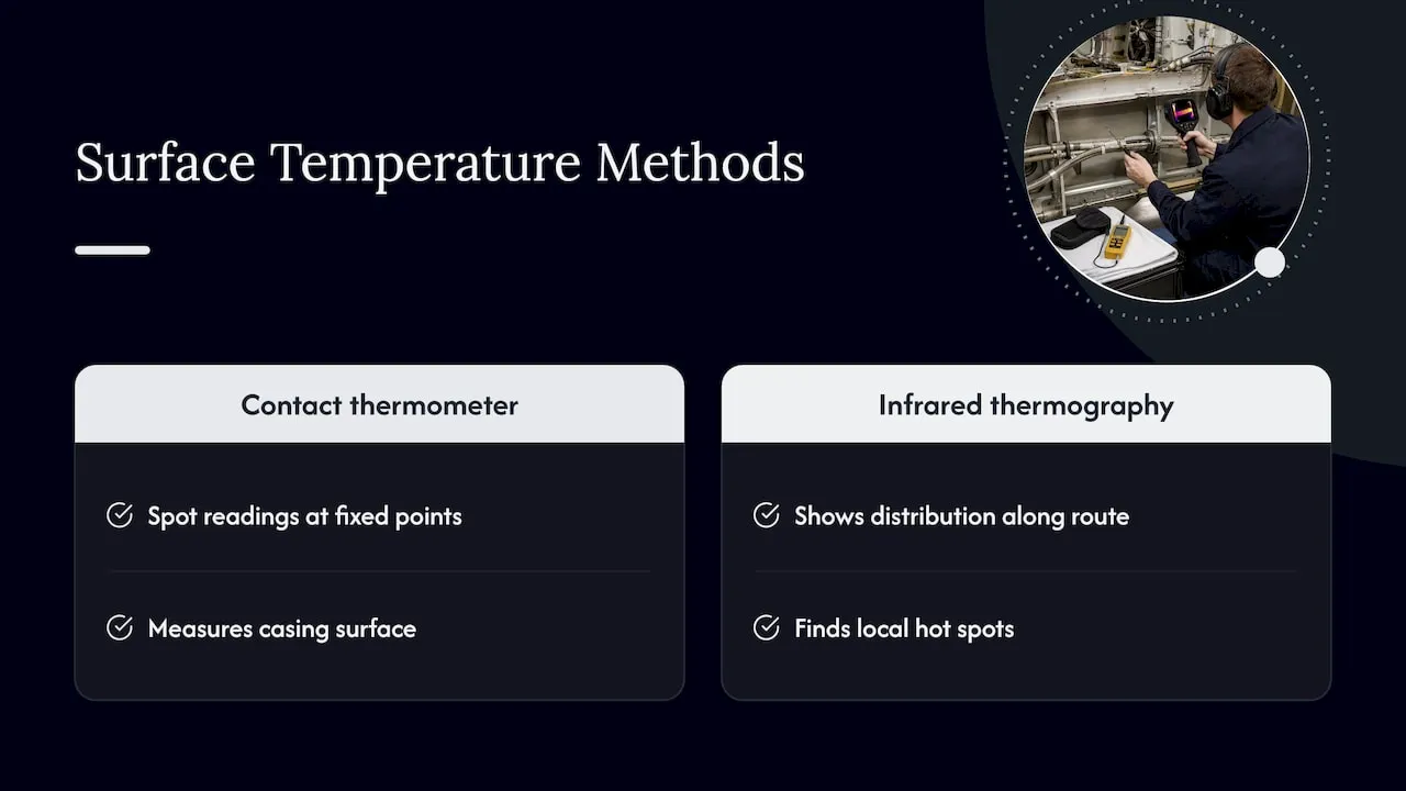
A contact surface temperature thermometer is adequate for spot readings at fixed points. Infrared thermography shows the distribution along the route and finds local hot spots. Both methods measure the casing surface, which is lower than the core temperature. The relationship between the two depends on the casing material and wall thickness and should be established on a test setup, not assumed.
Interpret the pattern
| Observed pattern | Likely meaning |
|---|---|
| Temperature rises, then levels at a repeatable plateau | Normal warm-up; compare plateau with baseline |
| Plateau higher than baseline at same load and ambient | Increased friction: lubrication, bend radius, misalignment |
| Continuous rise without plateau | Heat generation exceeds dissipation; stop and inspect |
| Rapid step increase shortly after start-up | Binding, overload, jammed driven element, insufficient grease |
| One local hot spot on the casing | Kink, tight bend, damaged casing or contact with a structure |
| Hot end fitting, cool shaft body | Bearing or coupling problem, side load, misalignment |
| Heating together with noise or vibration | Core damage, whip at critical speed, loose fitting |
The limit values themselves, such as maximum continuous temperature of grease and sheath, come from the manufacturer’s data. They should not be derived from forum experience.
Troubleshooting heating step by step
The sequence below goes from the least invasive check to disassembly. Work on any drive must follow the plant’s or maintenance organization’s procedures: isolate and lock out the drive before touching the shaft, and let hot components cool.
- Record the conditions. Speed, torque or motor current, duty cycle, ambient temperature, running time before the temperature was noted, and the measurement points.
- Compare with the baseline and the data sheet. If the plateau lies within the manufacturer’s limits and matches the baseline, no fault exists. If it does not, continue.
- Check the load. Measure motor current or torque. A driven element that binds or a changed process load explains many cases without any shaft defect.
- Inspect the routing. Look for bends below the minimum radius, kinks, casing resting against hot structures and missing supports. Bend severity is the most frequent installation cause.
- Check end fittings and alignment. The core must enter the coupling without side load. Misalignment produces a hot end fitting and an uneven wear pattern.
- Check lubrication. Dry core, hardened grease or grease contaminated with dirt raises friction. Relubrication intervals and grease type must follow the manufacturer’s specification. Grease reduces friction between core and casing, so a lack of it directly increases heat.
- Inspect the core and casing. Broken wires, discoloration from heat and flattened casing sections indicate damage. A damaged core should be replaced, not repaired.
- Re-test after correction. Run the same load and compare against the baseline.
When to stop operation
Operation should stop when the temperature continues to rise without a plateau, when the measured temperature approaches the limit of grease, sheath or seal named in the data sheet, when discoloration, smoke or smell appear, or when noise and vibration increase along with heat. In safety-relevant systems the stop criteria are set by the system’s maintenance documentation. The information to compare with the manufacturer’s technical limits is: rated and peak torque, maximum speed, minimum bend radius, permitted temperature range, duty cycle, lubrication type and interval, and the permitted end-fitting loads.
Reducing heating at the design stage
Most heating problems are cheaper to prevent in design than to correct in service.
- Shorten the shaft and reduce bends. Each additional meter and each additional bend adds friction. The length selection guide explains how routing and load interact.
- Keep bend radii well above the minimum at the tightest point, and keep that point away from the driving end where torque is highest.
- Size for torque with margin. Choosing a shaft that runs at a fraction of its rated torque lowers friction heat and fatigue.
- Specify the lubricant for the real temperature and speed range, and define the relubrication or replacement interval.
- Support the casing near the end fittings so the shaft enters the coupling without side load.
- Define the duty cycle in the specification, including worst-case continuous operation.
- Provide space for dissipation. Keep the casing away from hot components and avoid enclosing it in insulating material.
Further background on compact layouts is in the article on engineering compact drive solutions and on shaft flexibility in industrial drives.
Industrial finishing: the same mechanism, a different duty
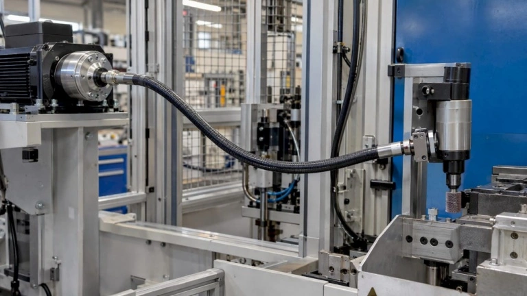
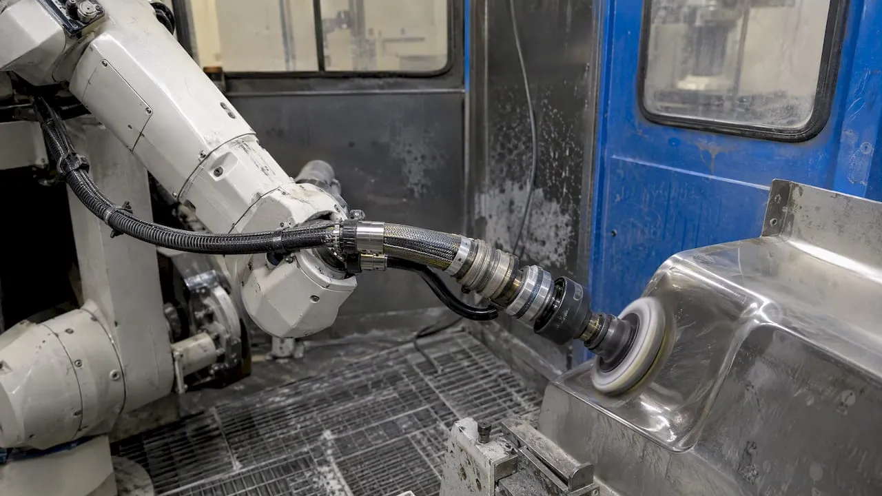
In deburring, grinding and polishing, flexible shafts typically run at high speed with changing loads and with the operator or a robot moving the tool. Heating there comes from sustained high speed, frequent changes of bend geometry and contamination by abrasive dust at the end fittings. The same baseline method applies: record a plateau for a defined tool and feed, then watch for deviation. Application detail is in the pages on flexible shaft design for tight-space finishing and industrial manufacturing applications.
Perspective: specify the thermal case with the shaft
In our experience with inquiries from machine builders and manufacturers, heating is rarely a question about the shaft alone. It results from the combination of routing, speed, torque, lubrication and duty cycle, and these are often defined late. We therefore ask for the following at the start of a project: required torque and speed including peaks, the planned route with bend radii and lengths, the coupling interfaces, the ambient temperature range and the duty cycle. With these data, a standard shaft can be checked against its limits, or a configuration can be defined for the particular case, for example a different core build, protective sheath or end fitting. A surface temperature reading taken on a prototype, with the conditions recorded, is among the most useful data for this evaluation.
— Uli
Specifying a shaft for a defined thermal case
For installations where bend radius, speed or temperature range lie outside catalog values, BIAX supplies custom solutions and prototypes as well as standard lines such as actuation shafts and flexible shaft core by the meter. Torque, speed, route, temperature range and duty cycle are the inputs needed for a technical assessment.
FAQ
Is it normal for a flexible shaft to get warm?
Yes. Friction between core wires and between core and casing always produces some heat, and a stable plateau after warm-up is expected. The plateau should be repeatable at the same load and ambient temperature. A continuing rise or a plateau above the recorded baseline indicates a fault or an operating point outside the specification.
What temperature is too high for a flexible shaft?
No universal value exists. The limit is set by the grease, the protective sheath, any seals and the end fittings, and it is stated in the manufacturer’s data for the specific shaft. The absolute temperature must be compared with these limits, not only the rise above ambient. See the temperature range guide for the parameters to define.
Can too small a bend radius cause overheating?
Yes. A smaller radius increases the contact force between core and casing, which raises friction and heat and shortens life. A technical article on flexible shafts reports that under minimum bending conditions only 30 percent of power is transmitted, the rest being lost as heat (source). Keep radii above the specified minimum.
Does more grease reduce heating?
Not necessarily. Grease reduces friction between core and casing, but the type, quantity and interval must follow the manufacturer’s specification, especially at high speed. An overfilled casing can raise churning losses. Lubrication for fast shafts is covered in the lubrication guide.
How should surface temperature be measured on a flexible shaft?
Use fixed measurement points on the casing, such as both ends, the tightest bend and a straight section, and record speed, torque and ambient temperature with each reading. Contact thermometers give spot values, and infrared thermography shows local hot spots. Compare readings with a baseline from a known-good assembly.
Contact
Technical questions on thermal limits, routing or custom configurations can be sent through the contact options on the BIAX Flexwellen website.
Sources
- Flexible Options with Flexible Shafts
- Identifying temperature problems in machines: data loggers as a troubleshooting aid
- Analyzing mechanical systems using infrared thermography
- TU Hamburg, academic work on flexible shafts
- US patent 4,424,045, flexible shaft casing assembly for tight radii
- EP0743443A1, thrust reverser synchronization shaft lock
- Wikipedia, Welle (Maschinenelement)
Recommended
- Flexible Shaft Temperature Range: A Specification Guide
- Flexible Shaft Failure Causes: 4 Triggers, Aerospace RCFA Clues
- For Engineers: Flexible Shaft Lubrication for Shafts Above 10,000 rpm
- Flexible Shaft Maintenance Process for Peak Performance
Related Topics
Send your spec inquiry
Custom flexible shafts for your application — we quote within 1 working day.