
Advantages of Torque Transmission for Machine Engineers
20 July 2026TL;DR:
- Effective torque transmission enhances energy efficiency and ensures precise, reliable machine operation. Proper sizing and maintenance extend component lifespan and minimize costly downtime. Using advanced gear systems and flexible shafts optimizes drive performance in confined or complex layouts.
Torque transmission is defined as the transfer of rotational force from a power source through mechanical components to a driven load, and its advantages directly determine the efficiency, accuracy, and service life of industrial machinery. For machine designers and manufacturing decision-makers, selecting the right torque transmission system affects energy consumption, component longevity, and production output. Modern gear systems, flexible shafts, and drive couplings each offer distinct performance profiles governed by established mechanical principles. Understanding these profiles is the foundation of sound drive system design.
1. Advantages of torque transmission in energy efficiency
High mechanical efficiency is the most measurable benefit of well-designed torque transmission. Modern gear systems achieve 97–99% mechanical efficiency, minimizing energy loss to heat and friction. That figure means less than 3% of input power is wasted per stage in helical and bevel gear configurations, which compounds favorably across multi-stage drivetrains.
Variable-speed control amplifies these gains further. VFDs on centrifugal pumps save approximately 66% pumping energy at 70% speed compared to throttled valve control. The savings follow the affinity laws, where power demand drops with the cube of speed reduction. Integrating variable frequency drives with optimized gear ratios is one of the highest-return investments available in industrial drive design.
Worm gears present a different picture. Their efficiency ranges from 50–90% depending on lead angle and lubrication conditions. Engineers specifying worm gear stages for high-duty-cycle applications should account for the additional thermal load and cooling requirements that lower efficiency introduces.
Pro Tip: When specifying a multi-stage gearbox, calculate cumulative efficiency across all stages before selecting motor size. A three-stage helical gearbox at 98% per stage delivers approximately 94% overall efficiency, which still justifies a smaller motor than a single-stage worm arrangement.
- Helical and bevel gear stages: 97–99% efficiency per stage
- Worm gear stages: 50–90% efficiency, load and lubrication dependent
- VFD integration on variable-torque loads: substantial energy reduction at partial speed
- Lubrication optimization: reduces churning losses at high shaft speeds
2. Precision and reliability benefits of effective torque transmission
Gear-based torque transmission eliminates slippage entirely. Positive gear engagement ensures exact speed ratios, which is critical for synchronized multi-axis equipment and precision manufacturing cells. Belt drives and friction couplings cannot match this characteristic under variable load conditions.
Backlash is the primary precision constraint in geared systems. Backlash-free bellows couplings and zero-backlash planetary stages are the standard solution for applications requiring tight positioning repeatability, such as aerospace flap actuation systems and valve override mechanisms. Selecting precision-grade components from the outset is more cost-effective than retrofitting after commissioning.
Vibration management is equally important. Torsional vibration from mismatched inertia ratios or resonant frequencies causes accelerated bearing wear and fatigue in shafts and housings. Proper coupling selection, including flexible shaft elements with defined torsional stiffness, attenuates these excitations before they reach sensitive components.
- Zero-backlash planetary stages: preferred for positioning and synchronization tasks
- Bellows couplings: transmit torque without angular play, suited for servo-driven axes
- Torsional flexibility in flexible shafts: absorbs vibration in confined or misaligned drive paths
- Positive gear engagement: eliminates drift and speed ratio error under load variation
Correct torque sizing improves operational safety, accuracy, and energy efficiency while preventing premature failure and excessive wear. Oversized components add weight and cost without proportional benefit, which is a common and avoidable design error.
3. Torque multiplication and speed control
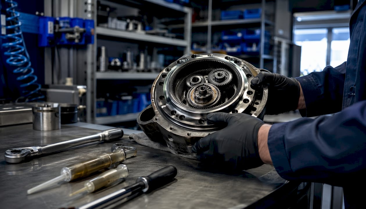
Torque multiplication is the mechanism that allows a small, high-speed motor to drive a large, slow-moving load. A 5:1 gear reducer converts 30 ft-lbs at 1,750 RPM into approximately 150 ft-lbs at 350 RPM, minus transmission losses. Power remains constant; torque and speed trade off inversely according to the relationship T = (HP × 5,252) / N.
This trade-off has direct consequences for machine layout. Higher gear reduction ratios allow smaller, lighter motors, which reduces frame size and material cost. The penalty is reduced output shaft speed, which can create throughput constraints in high-cycle applications. Balanced design requires matching the reduction ratio to both the torque requirement and the required production rate.
Planetary gear reducers offer the highest torque density in compact form. Planetary reducers transmit up to 3 times more torque than standard helical reducers of the same size, while reducing device volume by approximately 50%. That density makes them the preferred choice for confined installation environments, including aerospace actuation systems and robotic joint drives.
Pro Tip: For confined spaces where a rigid gearbox cannot be routed to the load, a flexible shaft solution from Biax-flexwellen transmits torque around bends and through tight geometries without requiring a straight-line drive path. This eliminates the need for additional bevel gear stages and reduces part count.
Direct drive vs. geared motor: choosing the right approach
Direct drive motors offer zero backlash and no gear friction losses, making them ideal for high-precision, high-response tasks. Gear motors yield higher torque density and better cost efficiency for low-speed, high-torque applications. The selection depends on whether the application prioritizes positioning accuracy or torque output at reduced speed.
| Criterion | Direct drive | Geared motor |
|---|---|---|
| Backlash | Zero | Present (reducible with precision stages) |
| Torque density | Lower | Higher |
| Efficiency losses | Minimal | 1–3% per gear stage |
| Best application | Servo axes, precision positioning | Conveyors, mixers, actuators |
| Cost at high torque | High | Lower |
4. Maintenance, service life, and operational costs
Proper torque sizing is the single most effective maintenance strategy available at the design stage. Correct torque sizing extends component life and reduces vibration-related wear across bearings, seals, and shaft couplings. An undersized drive runs continuously near its thermal limit, accelerating lubricant degradation and fatigue failure. An oversized drive wastes capital and adds inertia that degrades dynamic response.
Lubrication management determines long-term gear system efficiency. Churning losses from gears fighting lubricant drag contribute measurable efficiency loss at high speeds. Optimizing oil viscosity grade and fill level for the operating speed range reduces these losses without hardware changes. Lubrication management is as important as gear geometry for sustained transmission efficiency.
Gear systems outlast belt and hydraulic alternatives in high-duty-cycle industrial applications. Belts stretch and require periodic re-tensioning. Hydraulic circuits introduce fluid contamination risks and require filtration maintenance. A well-lubricated enclosed gear drive, sized correctly for its load, operates for years with minimal scheduled intervention beyond oil analysis and seal inspection.
- Correct torque sizing: prevents premature failure and reduces unplanned downtime
- Lubrication viscosity optimization: reduces churning losses and thermal load
- Enclosed gear drives: lower maintenance frequency than belt or hydraulic alternatives
- Torsional flexibility in flexible shafts: reduces shock load transmission to gearbox internals
For engineers specifying torque requirements for industrial machinery, a structured sizing workflow that accounts for peak torque, duty cycle, and thermal rating is the foundation of a reliable, low-maintenance drive system.
Key takeaways
Torque transmission efficiency, precision, and correct sizing are the three factors that determine whether a drive system delivers long-term reliability or generates recurring maintenance costs.
| Point | Details |
|---|---|
| Energy efficiency | Modern helical gear stages reach 97–99% efficiency; VFD integration cuts energy use further on variable-load applications. |
| Precision and no-slip | Positive gear engagement eliminates slippage and speed ratio drift, critical for synchronized and aerospace-grade systems. |
| Torque multiplication | Planetary reducers deliver up to 3× the torque of same-size helical units, enabling compact high-torque drive layouts. |
| Correct sizing | Oversizing wastes cost and adds inertia; undersizing accelerates wear. Match torque rating to actual peak load and duty cycle. |
| Lubrication management | Oil viscosity and fill level directly affect churning losses and gear service life at high operating speeds. |
An engineer’s perspective on torque transmission decisions
The most common mistake I see in drive system design is treating torque transmission as a commodity selection rather than a system-level decision. Engineers specify a gearbox from a catalog, match the rated torque to the motor output, and move on. What gets missed is the interaction between torsional stiffness, inertia ratio, and the dynamic load profile of the driven machine.
I have reviewed installations where a correctly rated gearbox failed within 18 months because the application involved frequent reversals with high inertia loads. The peak torque during deceleration exceeded the catalog rating by a factor the designer never calculated. The fix required either a larger unit or a torsionally compliant coupling to absorb the shock. Both solutions were available from the start at lower cost than the downtime and replacement.
Flexible shaft solutions are underused in machine design. Engineers default to rigid drivetrains with bevel gear stages to change direction, adding complexity and failure points. A flexible shaft drive routes torque around obstacles and through non-linear geometries without additional gear stages. For deburring, grinding, and finishing applications in confined spaces, this approach reduces part count and simplifies maintenance access.
The other area where I see consistent underinvestment is lubrication specification. Gear geometry gets detailed attention. Oil viscosity grade and change intervals often get copied from a previous project without checking whether the operating speed and temperature range match. Churning losses at high speed are real and measurable. Matching the lubricant to the actual operating conditions costs nothing at the design stage and pays back in efficiency and service life.
— Uli
Flexible shaft solutions for torque transmission in machine design
Biax-flexwellen designs and manufactures flexible shafts and drive solutions for industrial applications where rigid drivetrains cannot reach the load. Flexible shafts transmit torque reliably through bends, around obstacles, and into confined spaces, eliminating the need for additional bevel gear stages or complex linkage arrangements. They are used in deburring, grinding, polishing, and finishing processes where access geometry makes rigid shaft layouts impractical.
For machine builders specifying drive components, Biax-flexwellen provides engineering guidance on torque and RPM requirements, coupling interfaces, and shaft configuration. Standard and custom configurations are available. Engineers working on compact or hard-to-reach drive applications can review flexible shaft machine design solutions to evaluate whether a flexible shaft approach fits their torque transmission requirements.
FAQ
What are the main advantages of torque transmission in industrial machinery?
The main advantages are high energy efficiency, elimination of slippage through positive gear engagement, torque multiplication for compact drive layouts, and extended component life through correct sizing. Modern gear systems achieve 97–99% mechanical efficiency per stage.
How does torque multiplication work in a gear reducer?
A gear reducer trades output speed for increased output torque at a fixed ratio. A 5:1 reducer converts 30 ft-lbs at 1,750 RPM into approximately 150 ft-lbs at 350 RPM, with power remaining constant minus transmission losses.
Why does correct torque sizing matter for service life?
Undersized drives run near their thermal limit continuously, accelerating lubricant breakdown and fatigue failure. Oversized drives add unnecessary inertia and cost. Correct sizing matches the drive rating to the actual peak torque and duty cycle of the application.
When should engineers choose a flexible shaft over a rigid drivetrain?
A flexible shaft is the better choice when the drive path is non-linear, space is confined, or routing a rigid shaft would require additional bevel gear stages. Biax-flexwellen flexible shafts transmit torque through bends without added gear stages, reducing part count and maintenance points.
How does lubrication affect torque transmission efficiency?
Churning losses from gears displacing lubricant at high speeds create measurable efficiency losses. Matching oil viscosity and fill level to the actual operating speed and temperature range reduces these losses and extends gear service life without hardware changes.
Recommended
- Optimizing Torque Transmission Methods for Engineers
- Optimizing Torque Transmission: A How-To Guide for Engineers
- Industrial Torque Transmission Explained for Engineers
- Torque Transmission Guide for Mechanical Engineers
Related Topics
Send your spec inquiry
Custom flexible shafts for your application — we quote within 1 working day.


