End Support of Flexible Shafts: Coupling and Bearing Design
2 November 2026The end support of a flexible shaft is the arrangement that connects the shaft core to the drive and to the driven part, and that holds the shaft in position at both ends. It consists of a coupling or end fitting, a bearing or guide seat, and the transition into the protective tubing. Most field failures of flexible shaft installations start at these transitions, not in the shaft body, so the end design deserves the same attention as the shaft selection itself.
This article covers the functional principles, the design factors and the maintenance practice for flexible shaft ends. Aerospace actuation and confined installation environments serve as the main reference cases.
TL;DR
- The end support transfers torque and rotation into and out of the shaft core, and it must also control axial position, bend entry and alignment.
- Maximum torque, power, operating speed and winding direction determine how the couplings, bend protection and protective tubing are designed.
- Bearing seats are arranged as locating or non-locating (floating) supports. The choice decides how thermal growth and shaft length change are absorbed.
- Lubrication errors are the most frequent cause of bearing failure, so the lubrication concept belongs in the end design from the start.
- Aerospace uses such as thrust reverser actuation, flap and slat drives, valve override and synchronization shafts add routing, access and reliability constraints.
Table of Contents
- What end support means for a flexible shaft
- Design factors that determine the required end support
- Arranging coupling, bearing and guide at the shaft end
- Aerospace installations and confined environments
- Installation and maintenance at the shaft ends
- Specification checklist for the end support
- Perspective
- BIAX offer for flexible shaft drives
- FAQ
- Sources
What end support means for a flexible shaft
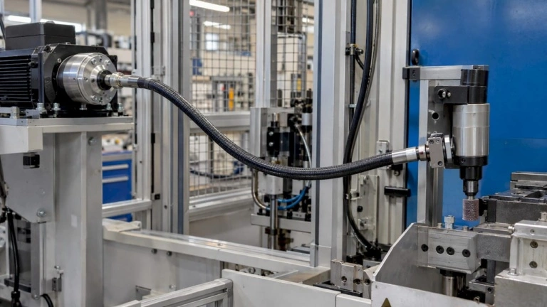
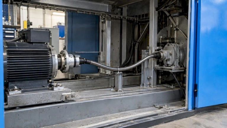
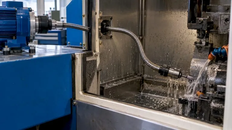
A flexible shaft consists of twisted metal wire layers, a core, which transmits rotation and torque along a curved path. According to Der Konstrukteur, such shafts are used in machine building, medical technology and automotive applications, and they can run continuously at speeds up to 50,000 min-1. The core alone does not make a drive. It needs defined connections at both ends.
The term end support covers four functions:
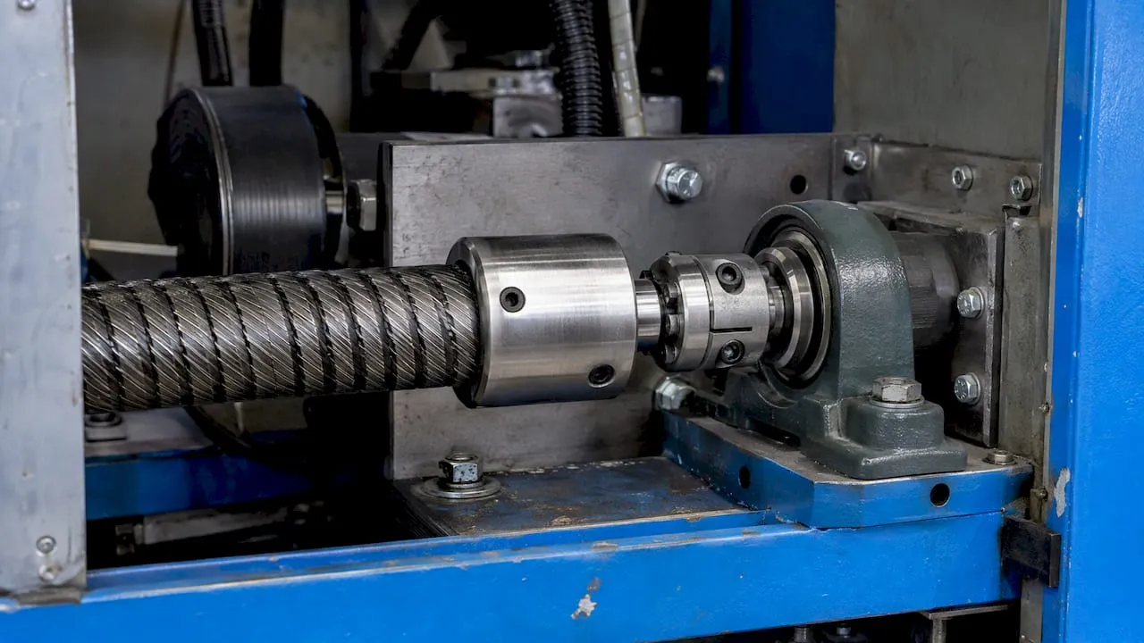
- Torque connection. A coupling, square, flat or keyed end, or a pressed and brazed fitting transfers torque between core and adjacent part.
- Axial and radial location. A bearing or guide seat holds the end so the core neither migrates axially nor whips radially.
- Bend entry control. A bend protection element limits the curvature at the point where the shaft leaves the rigid fitting. This is the location with the highest local stress.
- Sheath fixation. The protective tubing or sheath is clamped so it does not rotate with the core and does not shift under load.
The same shaft core can behave very differently depending on how these four functions are solved. A rigidly clamped end that forces an abrupt bend shortens service life. A well-supported end with a gradual transition lets the core carry its rated load.
Design factors that determine the required end support
The design starts from the load case. Der Konstrukteur states that the design is based on maximum torque, power and operating speed, and that couplings, bend protection, protective tubing, wire braid and shaft couplings are designed accordingly. Each parameter affects the end in a specific way.
Torque and power
Peak torque determines the size of the connection between core and fitting. Shock loads, for example from a jammed mechanism, must be covered by the fitting design and not only by the nominal torque. The end fitting is part of the torque chain, and the chain is only as strong as its weakest joint.
Speed
High speed raises demands on concentricity, balance of the end fitting and heat dissipation at the support. Whip and vibration grow when the core is unsupported over a free length. At the upper speed range, lubrication and guide design dominate the end concept. The BIAX guide on flexible shaft lubrication above 10,000 rpm treats this in detail.
Winding direction and direction of rotation
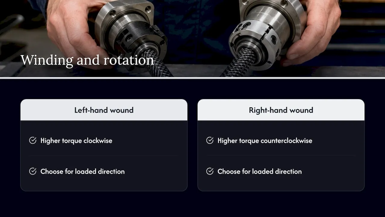
A flexible shaft does not perform identically in both directions. Der Konstrukteur notes that a shaft with a left-hand wound outer layer typically transmits higher torque in the clockwise direction, while a right-hand wound shaft performs better counterclockwise. The load direction at the end must therefore be defined before the shaft is specified. In an actuation drive that works under load in one direction and returns unloaded, the winding is chosen to match the loaded direction.
Bend radius and routing
Bend radius, total length and the number of bends decide how much torsional windup and friction the system shows. The end support sets the starting condition for the first bend. A straight lead-in section before the first curve reduces stress at the fitting. The BIAX article on length selection, routing, bend radius and load explains how these parameters interact.
Alignment offset
Flexible shafts can replace angle gears, chain drives or cardan joints when drive and driven component are not or only insufficiently aligned, as Der Konstrukteur points out. This is one reason they are used in confined installations. The end support must still hold the ends in a defined position, because the shaft compensates misalignment through its curvature, not through loose fixation.
Arranging coupling, bearing and guide at the shaft end
The bearing arrangement at a shaft end follows the established principles of rolling bearing design. The Schaeffler Mounting Handbook (December 2017) lists locating/non-locating, adjusted and floating arrangements as standard bearing arrangements. All three can be applied to the stub shaft or fitting at the end of a flexible shaft drive.
Locating and non-locating support
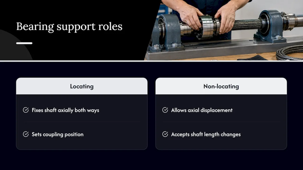
In a locating/non-locating arrangement, one bearing position fixes the shaft axially in both directions and the other allows axial displacement. For a flexible shaft drive, the practical meaning is simple: one end fixes the position of the coupling, and the other end accepts changes in length from temperature, load and routing. Schaeffler describes housing designs in which bearing seats are machined so that bearings can slide as floating bearings, while fixed rings create locating arrangements.
Housing and bearing selection
Separate bearing housings allow different bearing types to be installed in the same housing, according to WLT Wälzlagertechnik. For development programs this is useful: the housing envelope can be frozen early while the bearing type is adjusted after load and speed data are confirmed.
Coupling interface
The coupling interface must be defined together with the bearing position. Typical questions are:
- Is the connection rigid in torque with a defined axial clearance, or is it axially fixed?
- Which part of the assembly carries the radial reaction of the bent shaft?
- Does the coupling allow assembly and removal in the installed state?
Coupling documentation of other manufacturers also gives environmental guidance that applies to stored components. The Mädler coupling manual, for example, calls damp storage rooms unsuitable and recommends relative humidity below 65%. Spare fittings and shafts deserve the same storage discipline.
Sheath and bend protection
The sheath must be fixed against rotation and axial movement at the end. The bend protection (a spring or a molded sleeve) extends from the fitting over the first section of the sheath and creates a gradual change in stiffness. Without it, the bend concentrates directly behind the fitting.
Aerospace installations and confined environments
Aerospace actuation drives place several requirements on the end support at once: limited installation space, long service intervals, defined failure behavior and a need for reliable torque transfer over curved paths. The following use cases show how the end design reflects the function.
| Application | Function of the shaft | Main end-support concerns |
|---|---|---|
| Thrust reverser systems | Transmit actuation torque between drive unit and actuators along a curved path | Heat and vibration at fittings, secure sheath fixation, defined axial location |
| Flap and slat actuation | Transmit rotation along the structure between drive and actuator positions | Angular offset between stations, torque in both directions, synchronized end positions |
| Valve override systems | Allow manual or remote operation of a valve that is not directly accessible | Low-speed high-torque transfer, backlash, reliable engagement at the coupling |
| Synchronization shafts | Keep two or more actuators moving together | Torsional stiffness, winding direction, identical end conditions on both sides |
| Confined installations | Replace gears or joints where space is limited | Bend entry, clearance for the fitting, access for inspection |
The table lists functional concerns, not qualification requirements. Applicable approvals and test specifications come from the aircraft program and the responsible authority, and they are defined by the customer and the certification basis.
Actuation under load in one direction
For valve override and similar actuation tasks, load is mostly applied in one direction and at low speed. The winding direction of the core is chosen to suit the loaded direction, and the end fittings are designed for peak torque. BIAX describes this product family on its page for actuation shafts.
Synchronization
Where a shaft synchronizes two actuators, symmetry matters. Both ends should have the same fitting type, the same coupling clearance and comparable routing. Differences in torsional windup between two shafts show up as asynchronous movement, so the end supports should not introduce additional compliance on one side only.
Confined spaces
In confined spaces the fitting itself takes up the space the shaft was meant to save. The end support is designed to keep the rigid length as short as possible while maintaining enough bend protection. The BIAX article on machining in hard-to-reach spaces and the guide on flexible shaft design for tight spaces address the same geometric constraints from the production side.
Installation and maintenance at the shaft ends
Wear, overheating and failure at the ends are mostly caused by a small set of installation and lubrication errors.
Lubrication
According to Schaeffler/FAG, improper lubrication is the most frequent cause of bearing failure, and more than 80% of rolling bearings are grease-lubricated. The same source states that automatic lubrication systems can significantly extend bearing service life by preventing under- or over-lubrication. For the end support this means three design decisions:
- define the grease type and quantity at the bearing seat in the drawing;
- provide access for relubrication, or choose a sealed-for-life bearing;
- keep grease out of the sheath interior unless the shaft is specified for it.
Installation checks
- Verify coaxiality of the coupling seat and the bearing seat before the shaft is installed.
- Route the shaft without twisting it during installation, and fix the sheath only at the defined points.
- Check the bend radius at the first bend behind each fitting against the specified minimum.
- Rotate by hand, if the design allows it, and confirm free movement over the full length.
- Record the measured torque and temperature at first run, so later deviations can be identified.
Inspection indicators
Rising temperature at a fitting, increased running noise, discoloration of the sheath near the end and visible grease leakage indicate that the support is no longer working as designed. Maintenance intervals should be tied to these indicators and to the hours of operation. For a broader view of service tasks, see the BIAX article on the role of flexible shafts in maintenance.
Specification checklist for the end support
The following parameters allow a manufacturer to review an end support design. Missing values are the most common reason for follow-up questions.
| Parameter | Why it matters |
|---|---|
| Nominal and peak torque | Sizing of core and fitting connection |
| Speed range and duty cycle | Heat, lubrication and balance requirements |
| Direction of rotation under load | Selection of winding direction |
| Total length and bend radii | Windup, friction, first-bend stress |
| Coupling interface and tolerances | Connection to the adjacent component |
| Bearing arrangement (locating or floating) | Handling of length change and axial load |
| Ambient temperature, media, vibration | Material and lubricant selection |
| Installation access and inspection concept | Fitting design and maintenance intervals |
The BIAX guides on custom flexible shaft configuration and torque transmission best practices go through these inputs step by step.
Perspective
In our experience with inquiries from machine builders, the shaft core is rarely the open question. The open question is how the shaft ends are connected. A drawing that specifies torque and speed but leaves the coupling interface, the first bend and the sheath fixation undefined leads to several rounds of clarification.
We therefore treat the end support as part of the shaft design and not as an accessory. Coupling, bend protection and sheath fixation are configured together with the core, based on the load case. This is also the reason we work with customers on custom configurations and prototypes, where the interface can be adapted to the installation space instead of the installation space being adapted to a standard fitting.
For actuation and synchronization tasks, we recommend that the winding direction, the end fittings and the routing are reviewed in one step. Our engineers support this review with the data the customer can provide.
Uli
BIAX offer for flexible shaft drives
BIAX supplies flexible shafts by the meter, actuation shafts, drive and tool shafts, machine elements and custom solutions including prototypes and small batches. The end support can be defined together with the shaft. Relevant product pages are actuation shafts, custom solutions and prototypes and machine elements.
FAQ
What is the difference between a locating and a floating bearing at a flexible shaft end?
A locating bearing fixes the shaft position axially in both directions. A floating bearing permits axial displacement, usually through a sliding seat in the housing. Standard arrangements are described in the Schaeffler Mounting Handbook. In a flexible shaft drive, one end is typically the locating position and the other accommodates length change.
Which data is needed to specify the end fittings?
The minimum data set is nominal and peak torque, speed range, direction of rotation under load, total length, bend radii and the coupling interface of the adjacent parts. Ambient temperature, vibration and media exposure complete the specification. The checklist above lists these parameters.
Does the direction of rotation affect the shaft design?
Yes. According to Der Konstrukteur, a left-hand wound shaft typically transmits higher torque clockwise, and a right-hand wound shaft performs better counterclockwise. The loaded direction should be stated in the inquiry.
How should flexible shaft ends be lubricated?
The lubricant, quantity and relubrication access are defined at the bearing seat in the design stage, since improper lubrication is the most frequent cause of bearing failure according to Schaeffler/FAG. For shafts above 10,000 rpm, the BIAX lubrication guide gives further detail. Technical questions on a specific installation can be sent through the BIAX website.
Sources
- KONSTRUKTIONSELEMENTE I X, Der Konstrukteur 1-2/2015
- Mounting Handbook, Schaeffler, December 2017
- Lagergehäuse, Schaeffler Deutschland
- Lagergehäuse, WLT Wälzlagertechnik
- FAG Geräte und Dienstleistungen für Montage und Wartung
- Betriebsanleitung, Mädler
Recommended
- The Role of Shaft Couplings in Power Transmission
- Torque Transmission Best Practices for Flexible Shafts
- Shaft Design Considerations for Engineers: A Technical Guide
- Flexible Shafts for Tight Spaces: Boosting Precision
Related Topics
Send your spec inquiry
Custom flexible shafts for your application — we quote within 1 working day.