Backlash Compensation and Sizing: Engineers’ Reversing Flex Shaft Checklist
25 September 2026Flexible shafts handle reversing duty reliably when three conditions are met: backlash across direction changes is measured and compensated at the controller, the shaft’s torsional stiffness is balanced in both rotational directions, and the coupling and shaft are sized for peak reversal torque, not just continuous torque. Skip any of these checks and a flex shaft in reversierbetrieb will show position lag, uneven torque transfer, or premature fatigue. For engineered configurations that need bidirectional balance, Biax-flexwellen supports custom sizing from torque and duty-cycle data.
TL;DR:
- Shafts should be chosen with balanced torsional stiffness in both directions and sized based on peak reversal torque, not just continuous load.
- Torsional lag from elasticity and wire lay direction cause position errors during reversals that require proper controller compensation and load-side sensing.
- Incorrect sizing or neglecting acceleration peaks can lead to fatigue, uneven torque transfer, and premature shaft failure in reversing duty.
- Using a bidirectionally balanced core and verifying actual performance through field testing ensures reliable reverser operation.
- Custom-engineered flexible shafts are recommended for applications with high reversal frequency, tight tolerances, or significant load variations.
Table of Contents
- Mechanics of Direction Change: Backlash and Angle of Twist
- Mechanical Selection Constraints for Frequent Reversing Duty
- Sizing Workflow: Angle-of-Twist Formula and Reversal Factors
- Control Techniques for Reliable Reversierbetrieb
- Testing and Acceptance: Verifying Reversierbetrieb Performance
- BIAX Engineering Checklist for Reversing Applications
- Practical Tradeoffs From Field Engineering
- Get an Engineering Review for Your Reversing Drive
- Sources
- FAQ
Mechanics of Direction Change: Backlash and Angle of Twist
Reversing an axis exposes a gap between what the controller commands and what the load actually does. This gap has a name in motion control terminology: Umkehrlose, or backlash. Siemens motion technology documentation defines it as the offset introduced when a drive changes direction, and describes how Umkehrlosekompensation corrects the computed axis position so the load reaches the intended target after reversal.
A flex shaft adds a second, distinct source of error: torsional lag. Because the shaft core is elastic, it winds up under load before the far end starts moving. That windup is the Verdrehwinkel, or angle of twist, and it does not disappear when the controller’s backlash compensation is dialed in. The two effects stack.
Helically wound flex shaft cores compound this further. Most commercial cores use a wire lay optimized for one rotational direction. Running them in reverse changes the effective torsional response.
- Motor-side encoder position and load-side position diverge during every reversal, not just at startup.
- Torsional elasticity means the twist angle scales with torque, length, and shaft stiffness, and reverses sign when direction reverses.
- Wire lay direction in a standard helically wound core creates asymmetric stiffness between clockwise and counterclockwise rotation.
Mechanical Selection Constraints for Frequent Reversing Duty
Selecting a shaft for reversing duty means designing against four interacting failure modes rather than one continuous-torque rating.
- Torsional stiffness balance. A shaft optimized for one direction can transmit meaningfully less power in reverse. Product literature on flexible shaft construction notes that running a core against its preferred wire lay direction can drop transmitted power to 40 to 70 percent of forward-direction capacity unless the core is built for bidirectional balance.
- Fatigue life. Every reversal cycles torsional stress through zero and back, which accelerates fatigue compared to unidirectional running at the same RPM. Bend radius compounds the effect: a tighter installation radius combined with frequent reversals shortens expected service life faster than either factor alone.
- Damping versus reversal frequency. Higher taktfrequenz, meaning more reversals per minute, demands more damping in the shaft-coupling system to avoid resonant buildup between cycles.
- Welle-nabe connection integrity. The shaft-to-hub joint has to hold runout tolerance through repeated load reversals. Trade coverage of reversing-duty installations points to keyed or clamping hub connections, sized to the shaft diameter, as the more repeatable choice over friction-only fittings for maintaining runout accuracy across reversal cycles.
Pro Tip: Request a bidirectionally balanced core when reversal frequency exceeds a few cycles per second under load. The stiffness penalty of a standard helical lay in the “wrong” direction gets worse, not better, as duty cycle increases.
Sizing Workflow: Angle-of-Twist Formula and Reversal Factors
Sizing a flex shaft for reversierbetrieb starts with the standard torsion equation, then layers on reversal-specific safety margin.
The angle-of-twist formula is:
θ = τ · L / (C · J_shaft)
Where θ is the angle of twist in radians, τ is applied torque, L is shaft length, C is the shear modulus of the core material, and J_shaft is the polar moment of inertia of the shaft cross-section. Check θ against the maximum angular error your application tolerates at the load end. Explore the underlying torsion and torque relationships if you need the derivation before applying the formula to a specific core geometry.
Continuous torque alone underestimates the real load in reversing service. Acceleration spikes at every direction change add a peak torque component that a continuous-duty rating does not capture.
- Calculate peak torque from load inertia and commanded acceleration, not steady-state torque alone.
- Apply an operating factor to the coupling and shaft selection, not just the motor sizing.
- Recalculate θ at peak torque, not average torque, since angular error at the worst moment is what drives position accuracy.
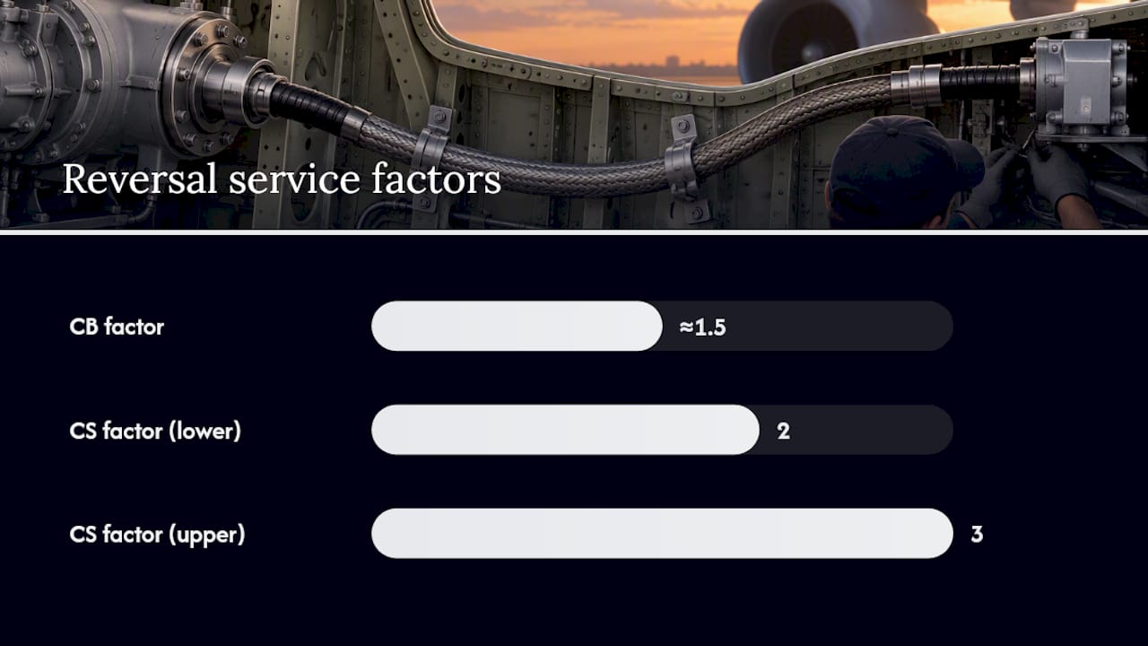
Coupling sizing guidance for reversing applications recommends a CB factor around 1.5 for frequent reversals, with CS service factors in the 2 to 3 range depending on shock loading.
Control Techniques for Reliable Reversierbetrieb
Mechanical sizing solves half the problem. The other half is at the controller, where Umkehrlosekompensation converts a measured backlash offset into a corrected target position after each direction change.
The Siemens implementation exposes a defined settings group for this: start and target positions for the compensation move, a compensation velocity, and an idle time (or wait time) before the compensated move executes. Getting these three settings right prevents overshoot and settling delay after reversal, according to the underlying motion technology documentation.
Sensor placement decides how much of the flex shaft’s torsional lag the compensation can actually see.
- A motor-side encoder alone measures motor position, not load position, so it cannot detect shaft windup and will under-compensate on a long or highly loaded flex shaft.
- A load-side encoder captures the real axis position, including torsional lag, and pairs better with Umkehrlosekompensation on flexible drivetrains.
- Where a load-side encoder is impractical, reduce velocity through the reversal window and extend idle time to let the shaft settle before the next move command.
Testing and Acceptance: Verifying Reversierbetrieb Performance
Before releasing a reversing axis to production, verify actual behavior against the sizing assumptions rather than trusting the calculation alone.
- Record motor position, load position when a load-side encoder is available, and torque or strain if the shaft is instrumented.
- Capture an oscilloscope or trend trace across several reversal cycles at production velocity and acceleration, not at reduced test speed.
- Check the PassingBacklash status flag if the controller exposes one; it indicates whether the axis is currently within the compensated backlash window.
- If position error at reversal exceeds tolerance, work through corrections in order: increase idle time first, then reduce acceleration, then reconsider sensor mode, and finally evaluate a stiffer or bidirectionally balanced shaft.
Pro Tip: Run the acceptance test at the actual application duty cycle, including realistic idle periods between reversals. A shaft that passes a slow, evenly spaced test can still show drift under a fast, irregular production cycle.
BIAX Engineering Checklist for Reversing Applications
A supplier can size a flex shaft for reversierbetrieb accurately only with complete load data up front. Provide continuous and peak torque, RPM range including direction, reversal frequency per minute, installation bend radius, coupling interface details at both ends, and required runout tolerance.
Request a bidirectionally balanced construction, a veredelte (finished) core treatment, or a prototype run when the application involves frequent reversals under load, tight positioning tolerance, or a confined installation path where standard catalog lengths do not fit. This applies broadly across industrial flexible shaft applications that involve deburring, grinding, and synchronized actuation.
- Torque data: continuous rating and calculated peak at commanded acceleration.
- Duty data: RPM range in both directions and reversal frequency.
- Geometry data: bend radius, overall length, and coupling interface specification at each end.
- Tolerance data: required runout and positional accuracy after reversal.
Practical Tradeoffs From Field Engineering
Most reversierbetrieb problems get blamed on the shaft when the real fault sits in the controller settings. Fix idle time and sensor mode before spending engineering hours on a marginal shaft upgrade.
The recurring mistakes: sizing to continuous torque and ignoring acceleration peaks, assuming a standard helical core performs identically in both directions, and skipping scope verification because the calculation looked fine on paper. Test with the real load and the real duty cycle. Nothing else tells you the truth.
— Uli
Get an Engineering Review for Your Reversing Drive
Standard catalog shafts assume one dominant rotation direction. A drive running reversierbetrieb under load, tight bend radius, or high reversal frequency often needs a construction engineered specifically for bidirectional torsional balance. That’s the gap Biax-flexwellen fills: custom-engineered flexible shaft cores sized from your actual torque, RPM, and reversal-frequency data, rather than a generic catalog rating.
If your application fits that profile, request a custom solution or prototype with your torque, RPM range, reversal frequency, bend radius, and coupling interface specification. For standard-length requirements, flexible shaft cores sold by meter may already cover the application. Submit your specification through the contact page for an engineering review.
Sources
The formulas and control settings in this article draw on a small set of primary references worth keeping on hand:
- Umkehrlosekompensation (Siemens motion technology documentation)
- Angle of twist formula reference (Formuladen)
- Belflex coupling sizing guidance (catalog excerpt)
FAQ
What Does Reversierbetrieb Mean for a Flex Shaft?
Reversierbetrieb refers to operating a driven axis so it repeatedly changes rotational direction, which introduces backlash at the controller and torsional lag inside the shaft itself. Both effects need separate handling: backlash through Umkehrlosekompensation, torsional lag through shaft sizing.
Can a Standard Flex Shaft Run in Both Directions?
Most standard helically wound cores have a preferred rotation direction and can transmit as little as 40 to 70 percent of rated power when run in reverse against the wire lay. Frequent bidirectional duty generally calls for a construction engineered for balanced torsional stiffness in both directions.
How Do You Calculate Angle of Twist for a Flex Shaft?
Angle of twist is calculated as θ = τ · L / (C · J_shaft), using applied torque, shaft length, shear modulus, and polar moment of inertia, following the standard torsion formula. Run the calculation at peak torque, including acceleration, not just continuous torque.
What Safety Factor Should I Use for Frequent Reversals?
Coupling sizing guidance recommends a CB factor around 1.5 for frequent reversing duty, with CS service factors typically between 2 and 3 depending on shock loading. Apply the factor to peak, not average, torque.
Does Biax-flexwellen Offer Custom Shafts for Reversing Applications?
Biax-flexwellen supplies bidirectionally balanced and veredelte core configurations engineered from torque, RPM, and reversal-frequency data submitted by the customer. Current pricing for custom and standard configurations is available directly through the product pages.
Recommended
- 4 Checks OEM Engineers Must Run for Axial Thrust in Flexible Shafts
- 7 Expert Flexible Shaft Maintenance Tips for Engineers
- Shaft Design Considerations for Engineers: A Technical Guide
- Custom Flexible Shaft Configuration Guide for Engineers
Related Topics
Send your spec inquiry
Custom flexible shafts for your application — we quote within 1 working day.


