
Noise Reduction in Drive Systems: A Practical Engineer’s Guide
27 July 2026TL;DR:
- Effective drive-system noise reduction begins by measuring baseline sound levels and identifying whether mechanical or electromagnetic sources dominate. Prioritize the highest-impact, lowest-cost fixes like control adjustments or mechanical tuning based on the source, validating results with repeat measurements before further modifications.
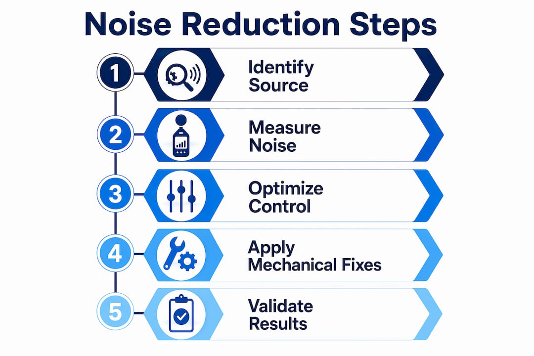
Effective noise reduction in drive systems follows a clear priority order: reduce source excitation first, then tune structural transfer paths, then address inverter-induced harmonics. For compact and aerospace installations, the sequence below applies immediately:
- Measure baseline SPL and run order tracking before any hardware change. A documented baseline at operating load and speed is the only reliable reference for validating improvements.
- Identify the dominant excitation order. Gear-mesh harmonics and electromagnetic (EM) carrier-frequency tones are the two most common culprits. A high-speed motor-plus-gear test recorded 86.2 dB at 5500 rpm and 200 Nm, with the 48th order (breathing mode) as the dominant structural response.
- Apply the highest-impact mechanical fix first: improve contact ratio, tighten gear tolerances, or add housing ribbing to shift modal frequencies away from excitation orders.
- Tune VFD settings: shift carrier frequency, enable dead-time compensation, and follow Rockwell Automation’s VFD installation guidance on shielded cables and common-mode chokes.
- Re-measure and confirm dBA reduction before committing to further changes.
Pro Tip: In confined installations where rigid shafts cannot be routed without housing contact, a flexible shaft decouples the drive housing from the driven assembly, removing a direct vibration transmission path without structural modifications.
Table of Contents
- Where does drive-system noise originate?
- How to measure and quantify noise in drive systems
- Mechanical and structural measures that reduce radiated noise
- Drive electronics and control strategies that reduce audible noise
- Design trade-offs and multidisciplinary considerations
- How to validate noise reduction results
- Step-by-step checklist for machine builders
- Research examples and aerospace design notes
- What to try first: prioritized recommendations
- Key Takeaways
- A practical perspective on drive-system noise projects
- How Biax-flexwellen supports noise-reduction projects
- Primary sources and further reading
Where does drive-system noise originate?
Drive-system noise arises from two coupled source families: mechanical excitation and electromagnetic excitation. Both feed energy into the same structural transfer path, so isolating which dominates at a given speed and load is the first diagnostic step.
Mechanical sources
- Gear-mesh harmonics: periodic force variation at the mesh frequency and its multiples, driven by transmission error, tooth deflection, and profile deviations.
- Meshing errors and assembly tolerances: pitch and runout errors amplify dynamic tooth loads; kinematic precision and contact ratio directly govern excitation magnitude.
- Shaft and bearing resonances: shaft bending modes and bearing defect frequencies can coincide with gear-mesh orders, amplifying radiated noise.
- Oil and air ejection: in high-speed spur gears, lubricant ejection at the mesh exit generates additional acoustic emission; increasing total tooth depth or adjusting backlash at the root can reduce ejection velocity, though load capacity trade-offs apply.
Electromagnetic sources
- Carrier-frequency radial EM forces: high-frequency current harmonics around the PWM carrier frequency generate radial force density on the stator, exciting structural modes.
- Dead-time-induced torque ripple: dead-time insertion in H-bridge PWM schemes distorts phase current, producing audible tonal content at multiples of the electrical frequency.
- Inverter sidebands: interactions between fundamental and carrier-frequency armature fields create sideband force components that can excite housing modes.
Key insight: System-level NVH engineering is shifting from isolated gear-noise fixes toward multidisciplinary workflows that integrate gear microgeometry, motor control, structural transfer paths, and psychoacoustics. Treating noise as a coupled excitation–transfer–perception chain prevents late-stage, high-cost fixes.
| Term | Definition |
|---|---|
| Order | Noise component at an integer multiple of shaft rotational frequency |
| SPL / dBA | Sound pressure level, A-weighted to approximate human hearing sensitivity |
| Carrier frequency | PWM switching frequency of the inverter, typically 2–20 kHz |
| Modal coincidence | Condition where a structural natural frequency aligns with an excitation order |
How to measure and quantify noise in drive systems
Use SPL (dBA), order tracking, and modal analysis as the primary metrics. Add narrowband power spectral density (PSD) for EM tonal content identification.
- Establish a calibrated measurement position: place a free-field microphone at 1 m from the gearbox housing surface, perpendicular to the largest radiating panel. For confined aerospace assemblies, a near-field microphone at 0.1 m is acceptable when far-field placement is obstructed.
- Mount accelerometers on the gearbox housing near bearing supports and on shaft supports. Use a tachometer signal for phase-referenced order tracking.
- Run a coast-down test from maximum operating speed to idle with constant load. This captures all resonance crossings and identifies which orders amplify at specific speeds.
- Conduct steady-state measurements at each rated operating point (torque and speed combinations). Record at least 10 seconds of data per point for reliable spectral averaging.
- Capture carrier-frequency tones using a current probe on one motor phase and a narrowband FFT centered on the carrier frequency. Compare the EM force spectrum to the structural FRF to identify modal coincidence.
| Instrument | Placement | Parameter measured |
|---|---|---|
| Calibrated microphone | 1 m from housing (or 0.1 m near-field) | SPL, dBA |
| Triaxial accelerometer | Gearbox housing, bearing supports | Vibration amplitude, ODS |
| Tachometer / encoder | Shaft | Rotational speed for order tracking |
| Current probe | Motor phase lead | Carrier-frequency harmonic content |
Pro Tip: In confined aerospace setups, use a miniature MEMS accelerometer bonded directly to the actuator housing rather than a contact microphone. This eliminates acoustic cross-talk from adjacent systems and gives a cleaner structural response for modal analysis.
Mechanical and structural measures that reduce radiated noise
Begin with kinematic precision. Improving contact ratio and controlling manufacturing tolerances reduces dynamic tooth loads at source, which lowers housing excitation before any structural treatment is needed. Profile modifications (tip relief, lead crowning) smooth the load transfer across the mesh cycle and reduce peak transmission error.
- Housing ribbing: adding ribs shifts panel natural frequencies away from dominant excitation orders. Rib position, height, and thickness all affect the resulting modal shift; FEM analysis before fabrication avoids ineffective rib placement.
- Panel segmentation: breaking large flat housing panels into smaller sections raises their natural frequencies and reduces the effective radiating area.
- Bearing preload and fit tolerances: tighter fits reduce dynamic clearance and lower the bearing’s contribution to broadband noise. Specify preload class and fit tolerance in the supplier data package.
- Shaft stiffness: increasing shaft diameter or shortening unsupported span raises the first bending critical speed, reducing the risk of resonance within the operating range.
Flexible-shaft considerations for confined installations
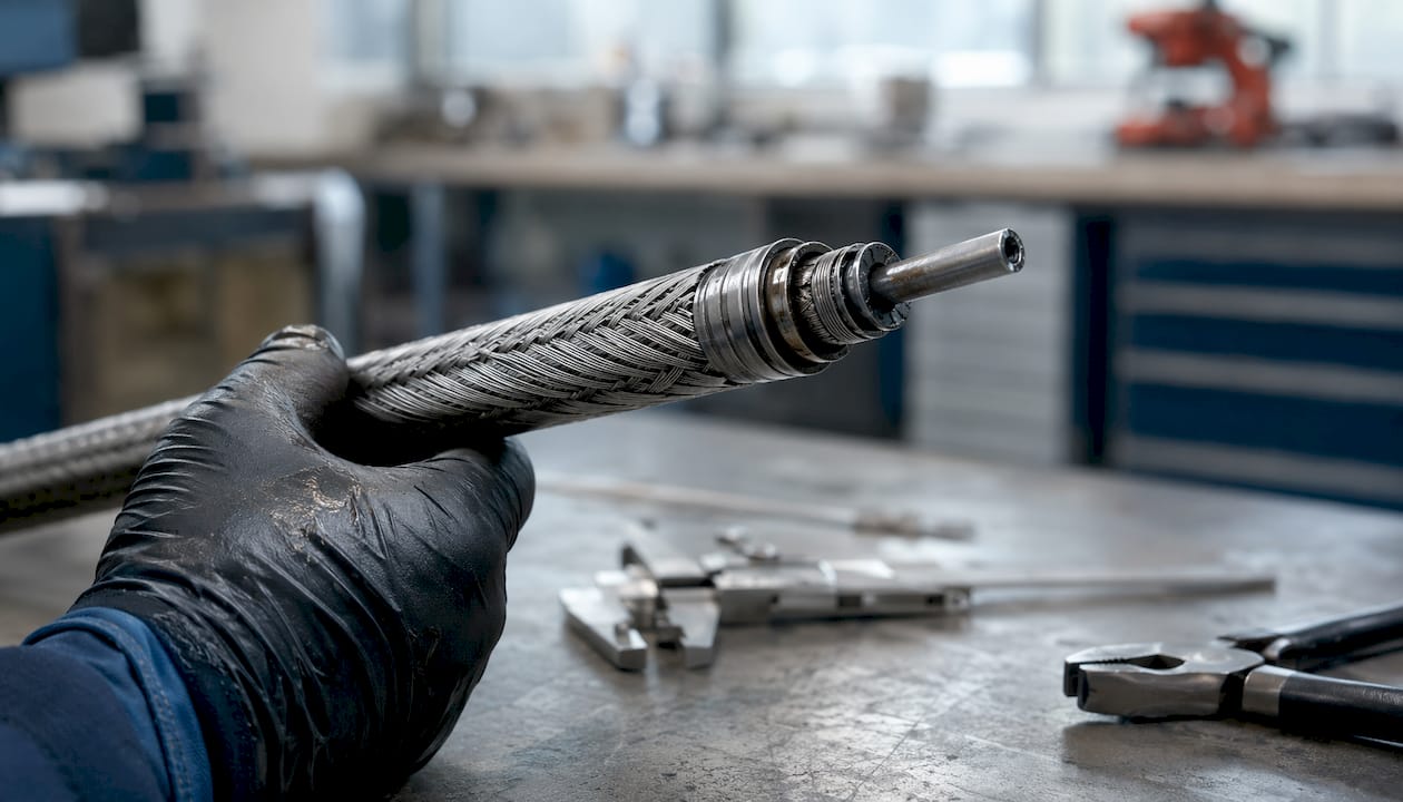
A flexible shaft for compact drive solutions introduces a compliant element between the drive motor and the driven tool or actuator. This compliance interrupts the rigid vibration transmission path and prevents housing resonances from coupling directly into the driven assembly. Key specification parameters:
- Torsional stiffness curve across the operating torque range
- Critical speed margins (minimum 20% separation from maximum operating speed)
- Allowable lateral deflection and minimum bend radius for the routed path
- Support interval recommendations from the shaft supplier
Pro Tip: Specify the shaft’s torsional stiffness at the actual operating torque, not at zero load. Stiffness is nonlinear in most flexible-shaft designs, and using the zero-load value can underestimate resonance risk at full torque.
Drive electronics and control strategies that reduce audible noise
Adjust the inverter and control layer to reduce carrier-related excitation before adding hardware. Hierarchical rotor-topology optimization combined with carrier-frequency shifting reduced measured carrier-frequency noise by 5.62 dBA from a 27.79 dBA baseline in a VFD-fed interior PMSM test rig.
VFD installation practices (Rockwell Automation guidance):
- Route motor power cables away from signal wiring; maintain physical separation throughout the cable run.
- Use shielded motor cables with the shield terminated at both ends.
- Use shielded signal wires with the shield terminated at one end only.
- Install common-mode chokes at the drive output where high-frequency ground currents are present.
- Lower PWM carrier frequency when audible tones near the carrier are the dominant complaint, accepting the thermal trade-off.
Control-side techniques:
- Carrier-frequency shifting: spreading the carrier frequency over a narrow band disperses tonal energy into broadband noise, reducing peak SPL at the carrier tone.
- Dead-time compensation via resonant controller: a resonant controller targets the harmonic component in phase current caused by dead-time insertion, reducing current distortion and the associated audible tone.
- Variable commutation modes (BLDC): dynamically switching between 120° and 150° trapezoidal commutation reduces the torque ripple associated with the Hi-Z interval.
- Continuous PWM modulation: continuous space-vector PWM reduces current ripple compared to discontinuous schemes, at the cost of higher switching losses.
Pro Tip: Validate every control change with an A/B measurement at the same operating point. Carrier-frequency shifts that reduce audible noise can increase EMI emissions or thermal stress on the inverter switches. Confirm compliance with applicable EMC standards before finalizing the setting.
| Control technique | Primary effect | Trade-off |
|---|---|---|
| Carrier-frequency shifting | Reduces tonal peak at carrier | May increase EMI emissions |
| Dead-time compensation | Reduces current distortion harmonics | Requires resonant controller tuning |
| Variable commutation | Reduces torque ripple at low speed | Limited to trapezoidal-commutated drives |
| Continuous PWM | Reduces current ripple | Higher switching losses |
Design trade-offs and multidisciplinary considerations
No single change eliminates drive-system noise. Lowering radiated SPL typically requires a combination of mass/stiffness adjustment, manufacturing precision, and control tuning, and each intervention carries a cost or performance trade-off.
- Added mass vs. stiffness: ribbing adds stiffness with minimal mass increase; adding mass to panels lowers natural frequencies, which can move resonances into the operating range rather than out of it.
- Tighter tolerances: improving gear kinematic precision reduces dynamic loads but increases manufacturing cost and lead time. The system-level NVH review supports data-driven and digital-twin workflows to navigate these multi-parameter interactions.
- Gear microgeometry changes: profile modifications that reduce transmission error can alter load distribution and affect tooth fatigue life. Validate with FEM before production.
- Control changes: carrier-frequency shifts and dead-time compensation improve acoustics but must be validated against EMI, thermal, and control-bandwidth constraints.
Prioritize interventions by ranking excitation magnitude (from order-tracking results), structural amplification (modal participation factor), and implementation cost. Address the highest-amplitude order with the lowest-cost fix first.
Pro Tip: For compact drive system designs, build a simple 3×3 matrix: excitation severity (low/medium/high) vs. implementation cost (low/medium/high). Start in the high-severity, low-cost cell.
How to validate noise reduction results
Verification requires the same instrumentation and operating conditions used for the baseline measurement. Run-up/coast-down tests confirm that resonance crossings have shifted or attenuated. Steady-state measurements at rated load confirm the dBA reduction at the operating point of interest.
- Repeat the coast-down test after each change and overlay order-tracked spectra against the baseline.
- Conduct modal testing (impact hammer or shaker) on the modified housing to confirm that natural frequencies have shifted as predicted.
- Measure ODS at the dominant order before and after structural changes to confirm reduced deflection amplitudes.
- Document acceptance criteria: for example, a targeted reduction of the dominant gear-mesh order by a specified dB value, or a total SPL reduction at the rated operating point.
- Record all test conditions (speed, torque, temperature, lubricant type and fill level) in a repeatable test protocol for supplier acceptance and commissioning.
| Validation method | What it confirms |
|---|---|
| Run-up / coast-down | Resonance crossing shift, order amplitude change |
| Steady-state SPL | Total dBA at rated operating point |
| Modal testing (FRF) | Natural frequency shift after structural change |
| ODS analysis | Deflection shape change at dominant order |
| Order-synchronous averaging | Gear-mesh harmonic amplitude before/after |
Pro Tip: For aerospace actuator assemblies, include a thermal soak at maximum operating temperature before the final acceptance measurement. Structural damping and bearing preload both change with temperature, and a room-temperature pass does not guarantee compliance at operating conditions.
Step-by-step checklist for machine builders
Immediate steps (0–30 days):
- Instrument the system and capture baseline SPL, order-tracked spectra, and a coast-down sweep.
- Identify the dominant order and its source (gear-mesh vs. EM carrier tone vs. bearing defect frequency).
- Apply the lowest-cost high-impact fix: adjust VFD carrier frequency or enable dead-time compensation for EM tones; specify tighter gear tolerances or add housing ribbing for mechanical orders.
Short-term steps (30–90 days):
- Commission prototype hardware changes (modified housing, revised gear microgeometry, or flexible-shaft routing change) and validate with repeat measurements.
- Confirm EMI and thermal compliance after any VFD setting changes.
Longer-term steps (>90 days):
- Conduct full modal survey of the revised assembly and update the FEM model.
- Document the validated test protocol for supplier acceptance and field commissioning.
Supplier questions for flexible-shaft orders:
- What is the torsional stiffness at the rated operating torque?
- What is the first critical speed, and what separation margin is recommended?
- What is the maximum allowable lateral deflection at the specified bend radius?
- What are the coupling interface dimensions and recommended support intervals?
- What lubrication type and service interval apply for the operating speed and torque?
Pro Tip: Request the torsional stiffness curve, not just a single stiffness value. The nonlinear behavior at low torque is where resonance risk is highest during run-up.
Research examples and aerospace design notes
The in-wheel reducer and motor drive system (IWRMDS) study recorded 86.2 dB at 5500 rpm and 200 Nm, with ODS analysis identifying the 48th order breathing mode as the dominant structural response. A segmented-skew rotor optimization reduced radial EM force for critical harmonics by nearly 30%, demonstrating that source-level rotor geometry changes can produce substantial SPL reductions without structural modifications.
The carrier-frequency hierarchical optimization study achieved a 5.62 dBA reduction from a 27.79 dBA baseline by combining rotor topology adjustment with carrier-frequency shifting. This approach applies directly to VFD-fed PMSM systems in industrial drives where carrier tones are the dominant acoustic complaint.
| Application | Primary noise source | Recommended first action |
|---|---|---|
| High-speed gear reducer | Gear-mesh harmonics, EM orders | ODS + order tracking; rotor/gear geometry |
| VFD-fed PMSM | Carrier-frequency EM force | Carrier shifting + dead-time compensation |
| Thrust reverser actuator | Gear-mesh, housing resonance | Modal survey; housing ribbing |
| Flap/slat actuation shaft | Torsional resonance, bearing noise | Critical speed margin; bearing preload |
| Confined synchronization shaft | Vibration transmission path | Flexible shaft routing; support intervals |
Aerospace design notes:
- Thrust reverser and flap/slat actuation assemblies operate in confined bays with limited access. Specify flexible shaft routing with support intervals that keep lateral deflection within the supplier’s allowable band at maximum operating load.
- For synchronization shafts in confined environments, verify critical speed separation at the maximum continuous speed, not just the rated speed.
- Service-life lubrication intervals for flexible shafts in aerospace actuator installations should be documented in the maintenance plan and confirmed with the shaft supplier for the specific operating temperature range.
Pro Tip: In aerospace actuator installations, favor mechanical tuning (housing ribbing, flexible-shaft routing) over control tuning when the drive controller is a certified unit with limited parameter access. Control changes on certified hardware require re-qualification.
What to try first: prioritized recommendations
Immediate actions:
- Measure first. No intervention is justified without a documented baseline SPL and order spectrum.
- Identify whether the dominant order is mechanical (gear-mesh) or electromagnetic (carrier-frequency tone). The fix is different for each.
- Apply the control-layer fix (carrier shifting, dead-time compensation) for EM tones. It requires no hardware and can be validated in hours.
For compact aerospace drives (first three actions):
- Run a coast-down order-track to identify the dominant order and its speed-dependent behavior.
- Enable dead-time compensation and adjust carrier frequency on the VFD; measure the dBA change.
- If the dominant order is mechanical, evaluate flexible-shaft routing or housing ribbing as the next step.
Machine-builder project timeline:
- 0–30 days: baseline measurement, order identification, VFD parameter adjustment.
- 30–90 days: prototype mechanical change (housing rib, gear tolerance, flexible-shaft routing), validation measurement.
- >90 days: full modal survey, FEM model update, supplier acceptance protocol, commissioning documentation.
Pro Tip: Sequence control changes before mechanical changes. Control adjustments are reversible and low-cost. If they achieve the target dBA reduction, mechanical modifications may not be needed.
Key Takeaways
Effective drive-system noise control requires source identification first, followed by the highest-impact fix at the lowest implementation cost, validated by repeat measurement at identical operating conditions.
| Point | Details |
|---|---|
| Measure before acting | Capture baseline SPL and order-tracked spectra at rated load before any hardware or control change. |
| Source identification drives priority | Gear-mesh orders and carrier-frequency EM tones require different fixes; misidentifying the source wastes time and budget. |
| Control changes first | Carrier-frequency shifting and dead-time compensation reduced measured noise by 5.62 dBA in a PMSM test rig with no hardware changes. |
| Structural tuning for mechanical orders | Housing ribbing shifts panel natural frequencies away from excitation orders; flexible-shaft routing removes direct vibration transmission paths in confined installations. |
| Biax-flexwellen flexible shafts | Biax-flexwellen supplies custom flexible shafts with specified torsional stiffness, critical speed data, and routing support for noise-sensitive compact and aerospace drive installations. |
A practical perspective on drive-system noise projects
The most common mistake in drive-system noise projects is skipping the measurement step and going straight to a hardware change based on experience from a previous project. Two systems with identical rated torque and speed can have completely different dominant orders depending on housing geometry, bearing selection, and inverter configuration. The 86.2 dB result from the IWRMDS study is a useful reference point, but the dominant order in that system (the 48th, a breathing mode) would not have been predicted without ODS testing. A housing rib placed without modal data is as likely to create a new resonance as to eliminate an existing one.
The other underestimated factor is the interaction between control changes and structural response. Shifting the carrier frequency disperses tonal energy, but if the new carrier frequency coincides with a housing panel resonance, the result can be worse than the baseline. Validate every control change with a full-spectrum measurement, not just a spot check at the original carrier tone frequency.
Flexible shafts are a practical tool in this context, not a last resort. In confined installations where rigid-shaft routing forces housing contact or creates unsupported spans that lower critical speed margins, a correctly specified flexible shaft resolves both the vibration transmission problem and the installation constraint simultaneously.
How Biax-flexwellen supports noise-reduction projects
Engineers working on noise-sensitive compact drive installations can submit technical inquiries to Biax-flexwellen with torque, RPM, mounting geometry, bend radius, and target operating conditions. Biax-flexwellen provides custom flexible shafts with defined torsional stiffness curves, critical speed data, and coupling interface specifications suited to confined and aerospace installations. Standard and custom configurations are available, with engineering support for routing and support-interval recommendations. For engineers ready to specify a flexible shaft or request a design review, the flexible shaft drive solutions page covers the full product range, and the contact page is the direct route for qualified technical inquiries.
Primary sources and further reading
-
In-Wheel NVH Study — NVH of In-Wheel Reducer and Motor Drive System. Start here if the primary concern is high-speed gear-plus-motor acoustic emission and rotor segmentation effects. Documents the 86.2 dB / 5500 rpm / 200 Nm result and the 30% EM force reduction from segmented-skew rotor optimization.
-
Carrier-Frequency Suppression — Hierarchical suppression of carrier frequency noise in VFD systems. Read this for control-layer and rotor-topology optimization targeting carrier-frequency EM noise. Documents the 5.62 dBA reduction from 27.79 dBA baseline.
-
System-Level NVH Review — System-Level Harmonic NVH Engineering in Electric Drivetrains (MDPI). The broadest reference: covers gear microgeometry, structural transfer paths, psychoacoustics, and digital-twin workflows. Read this for multidisciplinary context and housing ribbing evidence.
-
Gear Noise Fundamentals — Noise Reduction in Spur Gear Systems (MDPI). Covers contact ratio, kinematic precision, tolerance effects, and oil-ejection acoustics. Directly applicable to mechanical mitigation strategy.
-
VFD Installation Guidance — Rockwell Automation VFD Noise Reducing Installation Techniques. Practical cable routing, shielding, and common-mode choke guidance. Read this before commissioning any VFD-fed drive.
-
Motor Control Acoustics — Texas Instruments: Top 3 ways to reduce audible noise in motion control. Covers continuous PWM, dead-time compensation, and variable commutation modes with measured dBA results.
Reading priority: If the dominant noise source is mechanical, start with sources 3 and 4. If the dominant source is electromagnetic or inverter-related, start with sources 2, 5, and 6. For a new project with no prior diagnosis, start with source 3 for the system-level framework, then use source 1 as a measurement reference.
Recommended
- Industrial Drive System Basics for Engineers
- Streamline your industrial drive solution workflow for precision
- Optimizing Torque Transmission: A How-To Guide for Engineers
- Flexible drive solutions for efficient industrial design
Related Topics
Send your spec inquiry
Custom flexible shafts for your application — we quote within 1 working day.


