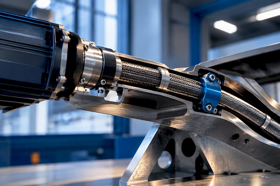
5 Tests Every Aerospace Engineer Should Run on Motor to Flex Shafts
21 September 2026A motoranschluss flexwelle is the interface that transmits torque and rotation from a motor into a flexible shaft, routed through confined or displaced installation paths to reach a remote tool, actuator, or driven component. Choosing one correctly comes down to a single rule: confirm the shaft meets nominal torque with an adequate safety factor, respects its minimum bending radius along the full route, and carries enough buckling margin under peak load before you look at coupling hardware at all.
TL;DR:
- Ensure the flexible shaft meets the required nominal and peak torque ratings with an appropriate safety factor before installation.
- Maintain the minimum bend radius specified by the manufacturer throughout the entire route to prevent efficiency loss and internal stress.
- Support the shaft with conduit or supports to increase buckling resistance and avoid helically buckling under load.
- Confirm that the shaft’s natural frequency stays outside the operating RPM range to prevent resonance-induced vibrations.
- Use flexible disk or diaphragm couplings with fail-safe bolt arrangements for critical aerospace or safety-sensitive applications.
Table of Contents
- When Does a Motor-to-Flex-Shaft Connection Make Sense?
- What Design Constraints Govern Torque, Bend Radius and Resonance?
- How Do You Size a Shaft and Set Alignment Tolerances?
- Which Motor Coupling Interface Should You Specify?
- What Installation Practices Prevent Common Failures?
- What Tests Confirm a Flex-Shaft Assembly Is Ready for Service?
- When Should You Rely on Supplier Engineering vs In-House Design?
- How Biax-flexwellen Supports Motor-to-Flex-Shaft Projects
- Selected Patents and Technical Papers
- Sources
- FAQ
When Does a Motor-to-Flex-Shaft Connection Make Sense?
Flexible shaft motor connections solve a specific problem: getting rotary power from a motor to a location the motor itself cannot reach or should not occupy. In aerospace platforms, that shows up in flap and slat actuation runs, valve override systems, accessory drive lines around engine nacelles, and synchronization shafts linking multiple actuators across a wing or control surface. In industrial machine building, the same logic applies to deburring and grinding toolheads that need to reach into cavities, brackets, or fixtures where a rigid drivetrain and its motor mass would not fit.
The core benefit is mass and inertia placement. Moving the motor away from the point of actuation reduces the moving mass at the working end, which matters directly for response time and structural loading in confined installations. A flexible shaft also tolerates a degree of misalignment between motor and load axis that a rigid coupling cannot absorb without added universal joints or gearing.
Flex-shaft connections are the wrong choice under a few conditions:
- Continuous, very high torque loads without a supporting conduit, where sustained cyclic stress accelerates core fatigue.
- Applications requiring zero backlash or absolute angular position feedback without additional encoding.
- Installations where bend radius cannot be maintained above the manufacturer’s minimum across the full route.
What Design Constraints Govern Torque, Bend Radius and Resonance?
Every motor-to-shaft specification starts with torque, but torque alone does not tell you whether the shaft will survive its installation. Five interacting constraints determine whether a given shaft diameter and construction will hold up in service.
Nominal and peak torque. Request nominal torque rating alongside peak or intermittent torque capacity, and apply a service factor. Aerospace applications generally warrant a higher safety margin than general industrial drives because duty cycles, temperature extremes, and vibration modes stack together rather than acting independently. Collins Aerospace’s application notes on rotary-wing drive shafts point out that flexible couplings in aerospace service must absorb torsional load and out-of-axis displacement at the same time, along with thermal expansion and structural deformation, rather than being sized against torque in isolation.
Bending radius and support spacing. Every flex shaft carries a manufacturer-defined minimum bending radius. Tighten below it, and transmission efficiency drops while internal wire stress rises. Support spacing along the route matters just as much as the radius itself.
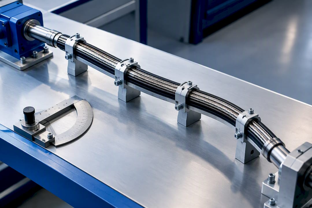
Critical buckling torque. Unsupported flexible shafts can buckle helically under torque well below their rated capacity. Increasing shaft diameter, adding a conduit, or reducing unsupported span all raise the buckling threshold.
Torsional stiffness and resonance. Natural frequency has to sit clear of the operating RPM band, or resonance amplifies vibration and shortens life.
Environmental and lifecycle factors. Temperature range, lubrication interval, and contamination exposure all affect service life and should be part of the initial spec, not an afterthought.
- Torque: nominal + peak + service factor
- Bend radius: minimum radius + support spacing
- Buckling: critical torque threshold + conduit strategy
- Dynamics: torsional stiffness + resonance clearance
- Environment: temperature, lubrication, contamination
Pro Tip: Ask the supplier for the critical buckling torque at your specific unsupported span length, not just the shaft’s generic rated torque. The two numbers can differ substantially once routing geometry enters the picture.
How Do You Size a Shaft and Set Alignment Tolerances?
Sizing a flexible shaft is not a lookup-table exercise once the route gets complicated. Aerospace and confined industrial installations introduce enough bend geometry and duty-cycle variation that the calculation needs real inputs, not assumptions.
- Gather the operating profile. Nominal torque, peak torque, duty cycle, RPM range, minimum bend radius available in the installation, and total route length all need to be fixed before a supplier can size anything meaningfully.
- Apply a service factor appropriate to the application. Aerospace-grade designs typically carry a higher margin than general industrial use, reflecting the accumulated effect of torsion, misalignment, and thermal load acting together, as Collins Aerospace notes.
- Define alignment tolerances at the motor interface. Radial runout and permissible angular misalignment both affect vibration and wear rate. A flexible shaft accommodates some misalignment, but exceeding its tolerance defeats the purpose of choosing a flexible interface over a rigid one.
- Translate the motor’s flange or shaft output specification into an end-fitting requirement. Motor shaft diameter, keyway dimensions, and flange bolt pattern all need to map cleanly onto the flex-shaft’s end fitting; mismatches here are one of the more common sources of installation delay.
- Require modal and buckling analysis from the supplier when the route includes multiple bends or long unsupported spans. A straightforward single-bend installation may not need it. A routed path through structural ribs or brackets usually does.
Guidance on how torque actually moves through a flexible shaft core, and where losses occur along the route, is covered in more detail in Biax-flexwellen’s explanation of torque transmission.
Which Motor Coupling Interface Should You Specify?
The interface between motor output and flexible shaft determines torque capacity, balance quality, and how straightforward certification will be, particularly on aerospace programs where every joint needs traceable documentation.
- Direct drive fittings (square drives, keyed shaft ends) are simple and low-cost, but their torque capacity at high RPM is limited by wear at the mechanical interface, and repeated engagement cycles can introduce backlash over time.
- Flange adapters and bolted interfaces give accurate, repeatable alignment and are the standard choice where aerospace attachment points require documented torque values and inspection access.
- Flexible-disk or diaphragm couplings tolerate angular and radial misalignment while transmitting torque through a thin flexible element rather than rigid teeth or splines. A bolt-pair arrangement in some diaphragm coupling designs provides fail-safe behavior: if the flexible disk itself fails, the remaining bolts can still carry torque, a pattern accepted in aircraft flap and slat transmission systems.
- Hybrid metal-composite adapters embed metal connectors into a composite shaft body through welded or form-fit joints, creating a redundant load path where certification requirements call for a proven metallic interface at the connection point, per hybrid drive shaft patent documentation.
Material selection at the coupling follows from the interface type: steel or titanium fittings for bolted flange connections, and matched composite laminates where the adapter bonds directly into a filament-wound shaft body.
What Installation Practices Prevent Common Failures?
Installation quality determines whether a correctly sized shaft actually delivers its rated performance over its service life. Most premature failures trace back to routing decisions made during installation, not to the shaft specification itself.
- Route in a single plane wherever possible. Multi-plane bends compound stress in ways that are difficult to predict analytically, and they accelerate wear at the point where bend direction changes.
- Set support spacing based on the supplier’s buckling data, not a generic rule of thumb. A conduit or series of guide supports raises the critical buckling torque and linearizes torque transmission along the route, as demonstrated in remote actuation research using conduit-supported flexible shafts.
- Place bearings or supports close to both the motor and the load end to isolate radial loads from the flexible core itself.
- Specify sealing and lubrication intervals matched to the environment. Contamination ingress at either end fitting is one of the more common causes of accelerated wear in industrial finishing applications.
- Run a commissioning check immediately after installation, before the assembly goes into service, to catch routing errors while they are still easy to correct.
Pro Tip: Check bend radius under the assembly’s worst-case installed position, not its nominal or relaxed position. A shaft that clears the minimum radius at rest can still violate it once brackets shift under vibration.
Further routing and support guidance is available in Biax-flexwellen’s best-practice notes on flexible shaft installation.
What Tests Confirm a Flex-Shaft Assembly Is Ready for Service?
A short acceptance test matrix catches most installation and sizing errors before a shaft goes into production use.
- Torque and torsional-deflection measurement. Pairing encoders or torque transducers before and after the shaft lets you directly measure twist against transmitted torque under real routing conditions, a method used in flexible shaft remote actuation test rigs.
- Runout and alignment checks, taken under both no-load and loaded conditions, since alignment error often only appears once torque is applied.
- Modal or resonance sweep across the full operating RPM range to confirm natural frequency stays clear of the running band.
- Buckling verification on the actual routed assembly, not a straight-line bench sample, since conduit performance and support spacing both affect the real threshold.
- Accelerated wear or life testing ahead of production acceptance, particularly for any assembly cycling continuously rather than intermittently.
Adding a conduit measurably raised nominal torque rating and linearized torque transmission in tested remote actuation prototypes, which is why buckling verification on the routed assembly matters more than a spec-sheet number alone.
When Should You Rely on Supplier Engineering vs In-House Design?
Bespoke composite diaphragms, high torque-density composite shafts, and certification documentation are areas where supplier engineering, such as BIAX’s, earns its place. In-house teams should retain control of interface geometry, test acceptance criteria, and installation constraints, since only the design team fully understands the surrounding assembly. A technical brief that states torque profile, RPM, route geometry, and required end-fitting type up front will move a supplier’s engineering response along far faster than an open-ended request.
— Uli
How Biax-flexwellen Supports Motor-to-Flex-Shaft Projects
Biax-flexwellen designs and manufactures both standard and custom flexible shafts, with engineering support covering torque, RPM, and coupling geometry for confined-installation drives. Where a catalog configuration does not match your route, its custom solutions and small-batch prototyping line covers everything from a single prototype through low-volume series production, backed by ISO 9001 quality processes.
A technical brief that gets a fast, accurate response should include: torque profile (nominal and peak), RPM range, route geometry and bend radii, environmental conditions, and the required end-fitting or flange interface. For standard shaft cores available without a custom engineering cycle, the meterware flexible shaft product line is worth checking first. Engineers ready to move forward with a specific torque, RPM, or coupling requirement can submit a technical inquiry through Biax-flexwellen’s contact page.
Selected Patents and Technical Papers
For deeper reference: the high torque density composite driveshaft patent and flexible disk fail-safe coupling patent cover coupling design principles referenced above.
Sources
- Collins Aerospace / drive shafts (industry application note)
- High torque density flexible composite driveshaft (patent)
FAQ
What Is a Motoranschluss Flexwelle?
It is the connection point where a motor’s rotary output transmits torque into a flexible shaft, allowing power to travel through a confined or offset route to a remote tool or actuator. The design must satisfy torque, bend radius, and buckling constraints simultaneously.
How Do I Choose the Right Bending Radius for a Flexible Shaft?
Stay above the manufacturer’s stated minimum bending radius across the entire route, including the assembly’s worst-case installed position under vibration. Going below that threshold both reduces transmission efficiency and raises internal wire stress.
Does Adding a Conduit Really Prevent Buckling?
Yes. Conduit support restrains helical buckling and raises the critical buckling torque threshold for a given shaft diameter, according to remote actuation research. It also linearizes torque transmission along the route.
What Coupling Type Offers Fail-Safe Behavior?
Flexible disk or diaphragm couplings with a bolt-pair arrangement can maintain torque transmission through the remaining bolts if the flexible element itself fails, a pattern documented in aircraft flap and slat coupling designs. This redundancy is one reason the design appears in aerospace accessory drives.
What Does a Custom Flexible Shaft Cost?
Pricing depends on torque rating, materials, and coupling configuration, so current prices are available directly through the Biax-flexwellen product pages. Submitting a technical brief with torque, RPM, and route geometry is the fastest way to get an accurate quote.
Recommended
- Five Tests That Reveal Flexible Shaft Faults for Aerospace Engineers
- 4 Checks OEM Engineers Must Run for Axial Thrust in Flexible Shafts
- 7 Expert Flexible Shaft Maintenance Tips for Engineers
- Torque, RPM, Bend Radius: Flex Shaft Tool Holder Specs for Aerospace
Related Topics
Send your spec inquiry
Custom flexible shafts for your application — we quote within 1 working day.


