3 Engineering Priorities for Flexible Shaft Vibration in Aerospace
11 September 2026Flexible shafts generate two dominant vibration types: torsional oscillation along the drive axis and flexural (whip) bending across unsupported spans. Both are manageable through geometry control, not exotic materials. The fastest corrective path is increasing bend radius, adding bearing-supported end fittings, balancing rotating tooling, and holding to a lubrication schedule. Address those four items first before investigating exotic damping solutions.
TL;DR:
- Keeping bend radius above manufacturer recommendations is crucial because tighter bends significantly increase internal wire stress and local resonance risks.
- Installing bearing-supported end fittings rather than plain bushings greatly suppresses low-order flexural modes and reduces whip development.
- Monitoring shaft vibration with accelerometers and conducting spectral analysis before and during operation helps identify natural frequencies and prevent resonance crossing.
- Common failure patterns include tight bends causing steady buzz, unsupported spans leading to moving whip, and lubrication breakdown resulting in high-pitched noise.
- Proper shaft design and installation, including material choice and routing, are more effective in controlling vibration than exotic damping solutions or material changes.
Table of Contents
- Understanding Schwingungen Flexwelle: Torsional and Flexural Vibration Modes
- Flexible Shafts Versus Rigid Drives Under Misalignment and Dynamic Load
- Bend Radius, Unsupported Length, and End Constraints in Shaft Routing
- Conduit, Support Hardware, Balancing, and Lubrication as Vibration Controls
- Measuring and Diagnosing Vibration in a Flexible Shaft Assembly
- Integration Patterns for Deburring, Confined Installations, and Aerospace Actuation
- RPM, Load, and the Torque Envelope of a Flexible Shaft
- Lubrication Practices That Extend Shaft Life and Reduce Vibration
- Common Failure Patterns and Their Vibration Symptoms
- Material and Design Choices That Shape Vibration Behavior
- Operating Environment Effects: Temperature and Contamination
- Standards and Test Methods for Vibration Limits
- An Engineering Perspective on Vibration Risk in Flexible Shaft Specification
- A Decision Checklist for Flexible Shaft Vibration
- Biax-flexwellen: Engineering Support for Vibration-Critical Shaft Specifications
- Sources
Understanding Schwingungen Flexwelle: Torsional and Flexural Vibration Modes
Schwingungen flexwelle, or flexible shaft vibrations, arise from two distinct physical mechanisms that often interact in the same installation. Torsional vibration is angular oscillation superimposed on the shaft’s rotation, typically excited by uneven load at the tool end or by torque ripple from the driving motor. Flexural vibration, often called whip, is lateral bending of the shaft axis itself, driven by mass eccentricity, unsupported span length, and proximity to a bending natural frequency.
Both modes depend heavily on construction. A flexible shaft core built from multiple layers of tightly wound wire behaves differently in torsion than a single-layer core, because layer count and winding direction change torsional stiffness independent of outer diameter. The surrounding conduit, whether a simple sheath or a rigid-walled guide tube, adds stiffness and mass that shifts the flexural natural frequency of the assembly, not just the bare core.
Key drivers of vibration behavior:
- Core construction (wire layer count, lay angle, hollow versus solid) sets torsional stiffness and shear modulus behavior.
- Conduit stiffness and wall thickness raise or lower the flexural natural frequency of the supported span.
- Unsupported length between end fittings determines how many bending mode shapes can form.
- Operating RPM relative to the first natural frequency determines whether resonance is likely.
Rule-of-thumb sizing based on bend radius and shaft diameter works for most industrial finishing tasks. Once a design approaches a critical speed or uses stepped/variable cross-sections, Timoshenko-beam-based modeling or FEM becomes necessary, since simpler Euler-Bernoulli assumptions underpredict resonance shifts at geometry transitions.
Flexible Shafts Versus Rigid Drives Under Misalignment and Dynamic Load
A rigid shaft with universal joints or a geared coupling holds tighter dynamic tolerance but cannot follow a curved path through a confined structure. A flexible shaft solves the routing problem at the cost of added compliance, which is exactly what generates the vibration questions engineers bring to this topic in the first place.
Flexible shafts perform best where:
- The drive path must curve around obstructions or reach into a housing with no straight-line access.
- Torque and RPM stay within moderate, unidirectional ranges.
- Some torsional compliance is acceptable or even beneficial for shock isolation.
Flexible shafts amplify dynamic response when spans run long and unsupported, when loading is directional rather than symmetric, or when the tool end presents an unbalanced mass. If the application demands continuous high power near a known critical speed, or requires bidirectional torque transmission with tight positional accuracy, a geared or rigid drive is usually the better specification choice.
Bend Radius, Unsupported Length, and End Constraints in Shaft Routing
Bend radius is the single most consequential routing variable. Manufacturer sizing tables consistently show that allowable torque falls as bend radius tightens, because a tighter radius increases internal wire stress and raises friction-driven heat that changes the effective stiffness of the core under load. Running a shaft below its rated minimum radius does not just shorten its life. It also shifts the local stiffness enough to move the flexural natural frequency into the operating range.
Design rules worth following:
- Keep bend radius at or above the manufacturer’s stated minimum for the shaft diameter and torque class, never treating the published figure as a rounding buffer.
- Limit unsupported length so the length-to-diameter ratio stays low enough to keep the first bending mode well above running speed.
- Terminate both ends in bearing-supported fittings rather than plain bushings, since a bearing constrains lateral motion and suppresses low-order flexural modes.
- Build in an RPM safety margin of at least 20 to 25 percent below any identified natural frequency, adjusting further if the load path is asymmetric.
Long unsupported spans deserve particular caution. Research on flexural-wave dispersion shows that bending energy can focus and amplify at reflective boundaries, which is a large part of why a shaft that looks fine at rest can develop a sharp local whip once it spins up past a certain speed. Avoid abrupt cross-section changes for the same reason: each step in geometry acts as a partial reflector for the traveling wave.
Pro Tip: When a shaft develops a whip pattern that seems to move location as RPM changes, that mobility itself is diagnostic. A fixed bulge usually points to eccentric loading; a bulge that migrates with speed almost always points to a resonance crossing.
Conduit, Support Hardware, Balancing, and Lubrication as Vibration Controls
The conduit is not a passive sheath. Interaction between the rotating core and the conduit’s inner wall provides real passive damping, and the grease film between them plays a direct role in how much high-frequency energy gets absorbed before it reaches the mounting points. Conduit selection should weigh wall stiffness against the flexural frequency target identified during routing design, not just abrasion resistance.
Support hardware does more work than most specifications give it credit for. A few points matter more than others:
- A bearing-supported end fitting acting as a thrust stop is often more effective at preventing whip than tightening the lubrication interval, because it removes a degree of freedom rather than damping an existing motion.
- Centering sleeves at intermediate points on long spans break up the unsupported length and push the first bending mode higher.
- A dedicated bearing/sleeve assembly at the output end, common in both hobby and industrial flexible-shaft accessories, doubles as a thrust bearing while carrying a grease nipple for the inner core, which keeps lubrication access simple during scheduled service.
- Coupling choice at each end affects how much torsional shock reaches the core; a slightly compliant coupling can reduce peak torsional stress without adding measurable lag.
Balancing rotating tooling matters more as RPM rises, since eccentric mass generates a forcing function that scales with the square of speed. A quick shop check, spinning the tool end by hand and watching for visible wobble before powering up, catches gross eccentricity before it becomes a resonance problem.
Field reports from shaft users, including hobby boat-modeling forums working with the same core physics, consistently point to the same failure pattern: sharp bends combined with undamped, unsupported spans produce premature wear and audible whip well before any formal test would flag it. Lubrication schedules should match duty cycle. Continuous high-RPM service warrants more frequent grease intervals than intermittent use, and grease nipple placement should allow service without disassembling the end fitting. Review maintenance intervals as part of the initial installation plan, not as an afterthought once vibration symptoms appear.
Measuring and Diagnosing Vibration in a Flexible Shaft Assembly
Confirming a vibration diagnosis requires instrumentation, not just visual inspection. A practical test sequence:
- Mount an accelerometer near each bearing-supported end fitting, oriented to capture both radial and axial motion, since torsional and flexural modes show up differently on each axis.
- Run a tachometer alongside the accelerometer to correlate any vibration peak with actual shaft speed rather than commanded speed.
- Perform a run-up and run-down sweep across the full operating range while logging the accelerometer signal, then convert the result to a frequency spectrum.
- Where available, use a laser vibrometer for non-contact confirmation on exposed shaft sections, particularly useful when physical accelerometer mounting would add unwanted mass.
Interpreting the resulting spectrum takes some judgment. Torsional harmonics typically appear as evenly spaced peaks tied to running speed and its integer multiples, while flexural resonance tends to show up as a single sharp peak at a fixed frequency that does not scale with RPM. Modal impact testing combined with run-up spectral analysis is standard practice for locating these natural frequencies before final installation sign-off, rather than discovering them in service.
Integration Patterns for Deburring, Confined Installations, and Aerospace Actuation
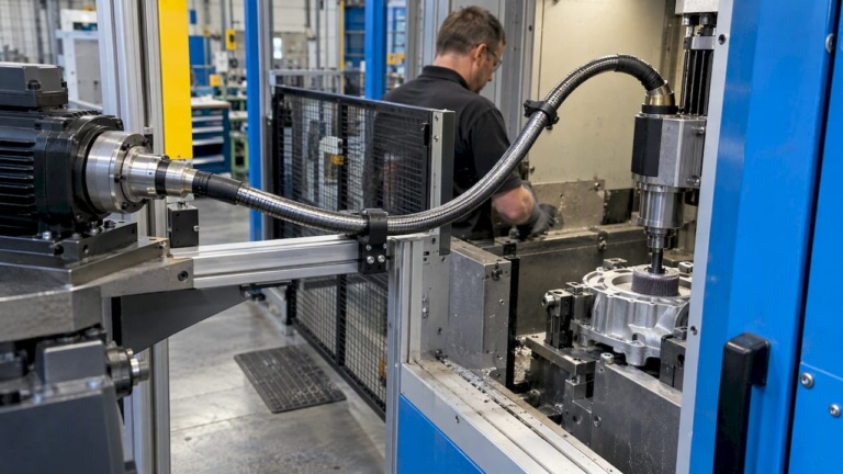
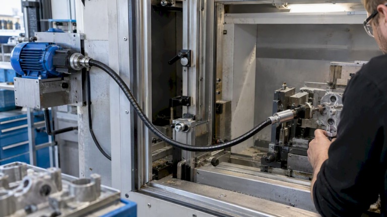
Deburring and grinding machines routing a flexible shaft to a handheld or fixture-mounted tool see vibration mostly from tool-end imbalance and from operators forcing tighter bends than the routing allows. Fixing this usually means relocating the support bracket closer to the tool end and confirming the actual installed bend radius against the spec sheet, not the intended one.
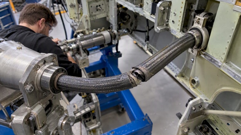
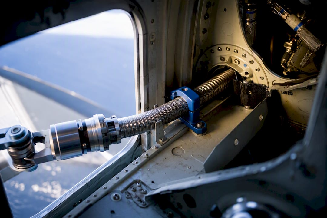
Constrained actuator applications, including valve override systems, and flap or slat actuation linkages use flexible shafts specifically to reduce packaging volume in tight airframe sections. These applications require end supports capable of reacting axial thrust as well as radial load, since actuation duty cycles introduce direction changes that a simple bushing cannot constrain.
A short integration checklist applies across both cases:
- Confirm routing radius against the manufacturer’s minimum before finalizing bracket locations.
- Design in service access for lubrication points without requiring full disassembly.
- Specify coupling type and shaft diameter against the actual torque and RPM envelope, including transient peaks, not just steady-state values.
RPM, Load, and the Torque Envelope of a Flexible Shaft
Allowable torque for a flexible shaft is not a fixed number. It is a curve that drops as RPM rises and as bend radius tightens, and manufacturer sizing tables treat these as coupled variables rather than independent limits. The maximum torque figure printed on a datasheet applies to a straight, unbent installation; any bend angle reduces that ceiling, and the reduction compounds with speed.
The mechanism behind this is straightforward. Higher RPM increases the frequency of stress reversal in the outer wire layers of the core, and tighter bends increase the amplitude of that stress reversal on each rotation. Run a shaft near its torque ceiling at low speed and it may perform acceptably for years. Push the same torque at a higher RPM through the same bend, and fatigue accumulates faster, often showing up first as increased vibration amplitude before any visible wire failure.
This is why a vibration complaint on an existing installation should always start with a torque and RPM audit, not a hardware swap. An engineer troubleshooting unexpected whip frequently finds that the process was upgraded to higher spindle speed without revisiting the shaft’s torque derating curve for the installed bend radius. The shaft itself may be identical to the one that ran quietly for years. Only the operating point changed.
Practical margin matters here. Specifying a shaft rated comfortably above the calculated torque and RPM requirement, rather than at the edge of its published envelope, gives room for the load variability that real production environments introduce. Review torque transmission best practices when sizing a shaft for a process that may see speed increases down the line, since resizing after the fact costs more than specifying correctly at the outset.
Lubrication Practices That Extend Shaft Life and Reduce Vibration
Grease inside a flexible shaft core does two jobs at once: it reduces friction between wire layers during flexing, and it provides a measure of passive damping that suppresses high-frequency vibration before it propagates to the end fittings. A dry or under-lubricated core loses both functions simultaneously, which is why lubrication neglect often shows up as a vibration complaint rather than a lubrication complaint.
Service intervals should track duty cycle rather than calendar time. A shaft in continuous high-RPM service accumulates internal friction and grease breakdown far faster than one used intermittently, even if both were installed on the same date. Grease nipple placement at the end fitting, positioned for access without removing the shaft from its housing, turns a scheduled task into a two-minute check rather than a machine-down event.
Grease type matters for temperature range and speed class. A grease formulated for high-speed service resists centrifugal migration away from the wire layers, while a general-purpose grease can separate and leave sections of the core running dry at sustained high RPM. Reapplying grease without first removing accumulated debris from the previous cycle is a common shortcut that shortens the benefit of the new application.
A basic maintenance checklist that ties directly to vibration control:
- Inspect grease condition at intervals matched to actual duty cycle, not a fixed calendar default.
- Confirm grease nipple access remains functional after any bracket or housing modification.
- Check for grease migration toward one end, a sign of imbalance or incorrect installation angle.
- Replace, rather than top off, grease that shows discoloration or metallic contamination from wire wear.
Following a structured maintenance checklist from installation onward catches early wear signs before they escalate into a vibration event that forces unplanned downtime.
Common Failure Patterns and Their Vibration Symptoms
Most flexible shaft failures trace back to one of three root causes: excessive bend angle, insufficient end support, or lubrication breakdown, and each produces a recognizable vibration signature before outright failure.
A shaft routed below its minimum bend radius typically shows a steady, speed-independent buzz that grows louder as duty cycle accumulates, driven by cyclic wire stress at the tight bend rather than by resonance. This differs from a resonance-driven whip, which appears and disappears at specific RPM bands and can vanish entirely outside that narrow window.
Insufficient end support produces a different pattern: a visible lateral bulge or whip that grows with speed and often shifts position as RPM changes, consistent with the shaft crossing through a flexural natural frequency rather than experiencing constant stress. This is the failure mode most closely tied to the wave-focusing behavior described earlier, where energy concentrates at points along an unsupported span.
Lubrication breakdown tends to announce itself acoustically before it shows up on an accelerometer. A dry core produces a rougher, higher-pitched noise under load, often before amplitude readings cross any meaningful threshold. Left unaddressed, this progresses to wire fatigue and eventually to core fracture, usually at the point of tightest bend or heaviest load concentration.
Catching these patterns early depends on knowing the baseline. A shaft that has run quietly for months and then develops a new noise or visible motion warrants investigation immediately, since the change itself is the diagnostic signal, not just the presence of some vibration.
Material and Design Choices That Shape Vibration Behavior
Core construction sets the ceiling on how much vibration control is achievable through installation alone. Multi-layer wound-wire cores offer more torsional compliance than a solid rod of equivalent diameter, which can be an advantage for shock isolation but requires tighter attention to flexural support since the same compliance that absorbs torsional shock also permits more lateral deflection under eccentric load.
Hollow-core designs reduce mass and can raise the flexural natural frequency relative to a solid core of the same outer diameter, since natural frequency scales with the ratio of stiffness to mass rather than stiffness alone. This makes hollow or reduced-mass cores attractive for high-RPM applications where pushing the first resonance above the operating range matters more than raw torsional stiffness.
Conduit material selection interacts with core choice rather than standing independently. A stiffer conduit constrains lateral core motion more tightly, which helps suppress low-order flexural modes but can transmit more vibration energy directly to the mounting structure if the conduit itself is rigidly clamped at both ends. A slightly more compliant conduit, paired with proper end bearing support, often damps better overall even though it looks less rigid on a datasheet.
End fitting geometry closes the loop on all of this. A fitting that provides genuine axial thrust support, not just radial location, prevents the small amount of end play that lets whip develop in the first place. Custom shaft configurations that match core type, conduit stiffness, and end fitting geometry to the specific torque, RPM, and routing constraints of an application consistently outperform a generic shaft forced into a demanding installation.
Operating Environment Effects: Temperature and Contamination
Temperature changes the mechanical behavior of both the grease and the conduit material, and both changes affect vibration indirectly rather than directly. Grease viscosity drops as temperature rises, which reduces its damping contribution right at the point in the duty cycle when higher friction from sustained operation is already generating heat. This is a compounding effect: a shaft that ran quietly during a cold startup can develop audible vibration an hour into continuous operation purely from thermal grease thinning.
Conduit material also responds to temperature. Polymer-based conduits soften at elevated temperature, reducing the lateral constraint they provide to the rotating core and effectively lowering the flexural natural frequency of the assembly while the machine is running hot. In cold environments, the same conduit can stiffen enough to change torsional compliance at startup, producing a brief vibration signature that disappears once the assembly warms to normal operating temperature.
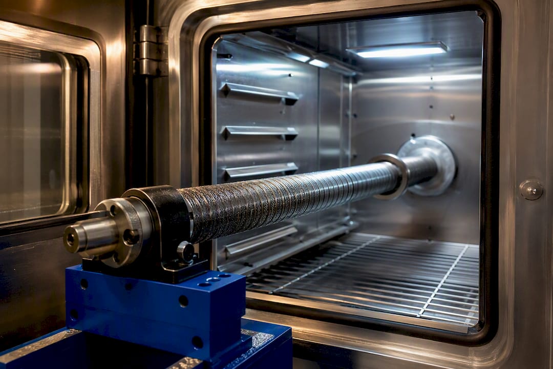
Contaminants introduce a different failure path. Abrasive particulate that migrates past a seal at the end fitting accelerates wear between the core and the conduit inner wall, and that wear increases clearance, which in turn increases the amplitude of any existing flexural mode. A shaft operating in a grinding or deburring environment, surrounded by metal fines and dust, needs seal integrity checked as part of the same inspection interval as lubrication, since a compromised seal quietly undermines both.
Installations in confined aerospace structures face a narrower but related concern: temperature swings across a flight envelope combined with limited access for inspection make selecting conduit and grease rated for the full expected range more important than in a climate-controlled shop floor application. A component that performs correctly at room temperature on a test bench is not automatically validated for the temperature extremes the same shaft will see in service.
Standards and Test Methods for Vibration Limits
No single universal numeric vibration limit applies across all flexible shaft applications, because acceptable vibration amplitude depends on the mounting structure’s sensitivity, the criticality of the driven tool, and the duty cycle involved. Instead, engineering practice relies on establishing an application-specific baseline through modal testing, then setting acceptance limits relative to that baseline rather than to a generic industry number.
The measurement methods described earlier, accelerometer-based run-up spectral analysis, tachometer correlation, and modal impact testing, form the practical foundation for this baseline approach. A new installation should be tested at commissioning to record its natural frequencies and typical operating amplitude, and that record becomes the reference point for future condition monitoring rather than a one-time compliance checkbox.
For applications with tighter tolerance requirements, particularly aerospace actuation linkages operating in confined structural sections, the modeling approaches referenced earlier become part of the acceptance process rather than just a design tool. Timoshenko-beam modeling validated against measured modal data gives a documented basis for confirming that a given shaft configuration keeps its natural frequencies safely clear of the operating range across the full RPM envelope, including transient conditions during actuation events.
Where an installation must integrate with a broader machine control system, vibration monitoring can also feed into a condition-based maintenance schedule, flagging a developing resonance or bearing wear before it produces an unplanned shutdown. This shifts vibration testing from a one-time acceptance gate to an ongoing diagnostic input, which fits naturally with the maintenance interval discipline covered earlier in this guide.
An Engineering Perspective on Vibration Risk in Flexible Shaft Specification
Vibration problems in flexible shafts are rarely a materials failure. They are almost always a specification gap, a bend radius pushed past its rating, an end fitting chosen for cost rather than axial support, or an RPM increase applied without revisiting the torque derating curve. A supplier engineering review typically starts by checking exactly these items: the specified torque and RPM against the installed bend radius, the end fitting’s ability to react axial thrust, and whether the routing plan leaves any span long enough to invite a resonance crossing. Custom configurations and end-fitting design exist precisely to close these gaps before installation, not to compensate for them afterward. Engineers working through a difficult routing problem, particularly in confined aerospace or actuation environments, benefit from a technical review before finalizing bracket locations. Reach out through the BIAX contact page for a spec review on a specific application.
— Uli
A Decision Checklist for Flexible Shaft Vibration
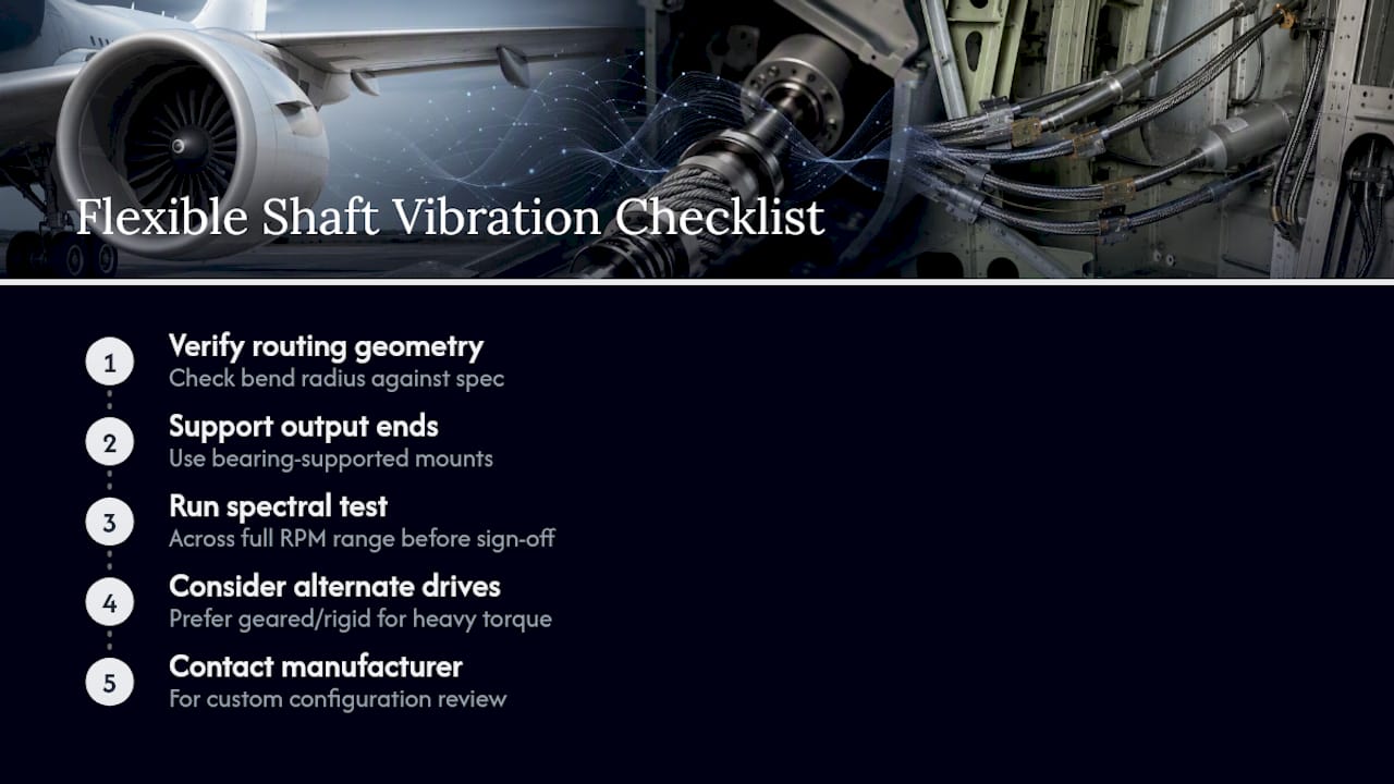
Three priorities in order: verify routing geometry and bend radius against spec, fit bearing-supported output ends, and run a spectral test across the full RPM range before sign-off. If the application needs bidirectional heavy torque or continuous operation near a critical speed, a geared or rigid drive deserves serious consideration instead. For a custom configuration review, contact the manufacturer directly.
Biax-flexwellen: Engineering Support for Vibration-Critical Shaft Specifications
Biax-flexwellen designs custom and standard flexible shafts for engineers who need measurable control over torque, RPM, and vibration behavior rather than a generic catalog part forced into a demanding installation. The advantage over sourcing a standard shaft and troubleshooting vibration afterward is straightforward: engineering input on bend radius, end-fitting geometry, and coupling interface happens before the shaft is built, not after a resonance problem shows up on the shop floor.
This fits engineers specifying shafts for deburring and grinding equipment, confined machine housings, or actuation linkages where axial thrust support and RPM safety margin both matter. Review how custom flexible shaft design addresses torque, RPM, and end-fitting requirements, then submit a spec through the BIAX contact form for an engineering review of a specific application.
Sources
- Flexible Shaft Components (Su hner components)
- Flexural wave focusing research (Phys. Rev. Applied)
- Modeling of flexible waveguides for ultrasonic vibrations transmission (ScienceDirect)
Recommended
- Five Tests That Reveal Flexible Shaft Faults for Aerospace Engineers
- Torque Transmission Best Practices for Flexible Shafts
- How to Select Flexible Shafts for Precision Machinery
Related Topics
Send your spec inquiry
Custom flexible shafts for your application — we quote within 1 working day.