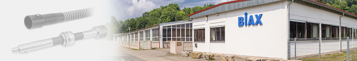
Hand control shafts

Construction / function
Hand wheel side

A hand wheel or a lever can be mounted at the hand wheel side (Pos. 1).
In your machine or installation you only need a hole fitting for the hose sleeve (Pos. 2).
The hand wheel shaft is placed into the hole and fixed with two nuts (Pos. 3).
The bolt can be supplied in different diameters.
Output side
The shaft coupling (Pos. 4) is asembled to the component to be controled.
The shaft coupling can be supplied with different drilling diameters.
For an optimized performance the shaft coupling can be individually adapted.
Shaft core
The shaft core (Pos. 5) is stiff against torsion and allows precise adjustment even at high torque.
Standard diameters (ØD1) are 5.0 mm, 8.0 mm und 16.0 mm.
Protective tube
The protective tube (Pos. 6) is very stable and can be fixed to the machine or installation by means of hose clamps.
| shaft core diameter (ØD1) | protective tube diameter (ØD2) |
|---|---|
| 5,0 mm | 8,8 mm |
| 8,0 mm | 13,5 mm |
| 16,0 mm | 22,0 mm |
Length
The hand wheel shafts can be produced up to a length (L) of 10 meters.
Application examples
Hand wheel shafts can be used for many different tasks in mechanical and plant engineering:
- Adjustment of valves
- Adjustment of machines and plants during operation
- Movement of controls outside hazard areas
- Emergency actuation in case of power failure
