Flexible Shaft Failure Causes: 4 Triggers, Aerospace RCFA Clues
12 October 2026The most likely root cause of a flexible shaft failure is fatigue from cyclic bending and torsion, frequently compounded by misalignment, stress concentrations, corrosion, or wear. If a shaft has failed, stop operation immediately, preserve the fractured components and machine state, photograph the installation before disturbing it, and tag all parts for failure analysis. These first steps protect the evidence needed for an accurate diagnosis, and engineering support from BIAX Flexwellen is available when a redesign is warranted.
TL;DR:
- Beach marks and a clear origin point indicate progressive fatigue, while coarse, granular fracture zones suggest overload; correlate both with operating history before concluding.
- Collect lubricant and debris samples, review earlier vibration records, and measure runout and alignment; bearing and coupling wear can expose chronic imbalance.
- Use magnetic particle inspection for near surface cracks in ferromagnetic shafts, while dye penetrant checks accessible surfaces and borescopes inspect hidden bores.
- Send the fractured section, service history, and samples for analysis when the origin is unclear, failures recur, or engineers are considering design changes.
- Correcting alignment, reducing deflection through adequate stiffness, and balancing the rotor can address common causes more reliably than simply choosing stronger material.
Table of Contents
- Common failure modes for flexible shafts
- Diagnosing damage: reading the fracture and secondary evidence
- Inspection and testing methods (on-site and lab)
- Root-cause analysis workflow for flexible-shaft failures
- Prevention: design, assembly, and maintenance measures to avoid recurrence
- Applying these guidelines in aerospace and confined installations
- Engineering support for custom flexible-shaft solutions
- FAQ
- Sources
Common failure modes for flexible shafts
Fatigue fracture is the dominant failure mechanism in shafts across mechanical equipment, and it accounts for most of the failures engineers encounter during root-cause investigations according to a systematic review of shaft failure mechanisms. Rotating shafts under bending loads experience fully reversed stress cycles with every revolution, so even moderate alternating stress below the material’s yield strength can nucleate a microcrack after enough cycles. The crack then grows incrementally until the remaining cross-section can no longer support the load, at which point final fracture occurs suddenly.
Overload failure differs fundamentally from fatigue. It results from a single load event that exceeds the material’s ultimate strength, producing a fracture surface without the progressive crack growth seen in fatigue, as outlined in guidance on shaft failure causes. Distinguishing the two mechanisms early directs the rest of the investigation.
Several conditions commonly initiate or accelerate these failures:
- Geometric stress raisers, including keyways, retaining-ring grooves, spline roots, and abrupt diameter transitions, concentrate local stress well above the nominal calculated value.
- Corrosion and corrosion fatigue reduce the effective cross-section and create surface pits that act as crack-initiation sites under cyclic load.
- Wear and fretting at coupling interfaces and bearing journals generate surface damage that lowers local fatigue strength over time.
- Manufacturing and heat-treatment defects, such as inclusions, decarburization, or improper case depth, reduce the material’s inherent fatigue resistance before the shaft ever enters service.
For flexible shafts specifically, tight bend radii and confined routing paths add superimposed bending stress to the baseline torsional load, which is why misalignment and installation geometry deserve early attention in any investigation.
Diagnosing damage: reading the fracture and secondary evidence
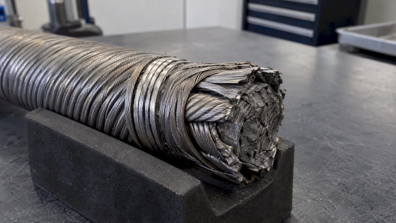
Fracture-surface features tell much of the story before any lab work begins. Progressive fatigue cracks typically show beach marks, concentric ridges that record successive crack-front positions, radiating outward from an identifiable origin point. Torsional failures often display a helical or twisted fracture plane distinct from the flatter planes typical of bending fatigue. A coarse, granular, or fibrous final-fracture zone generally indicates the overload region where the remaining ligament failed in a single event, a distinction confirmed in practical shaft-failure analysis.
Fracture appearance alone is rarely conclusive. Secondary evidence should be collected and correlated:
- Bearing and coupling wear patterns, which can reveal chronic misalignment or unbalance.
- Lubricant and wear-debris samples, since particle analysis can expose a transient lubrication failure or contamination event that accelerated crack initiation.
- Vibration signatures recorded before the failure, if available from condition-monitoring systems.
- Runout and unbalance measurements taken on the failed assembly or its replacement.
A practical triage sequence follows: document the installation in place, mark the fracture origin on the part itself, preserve all fragments without cleaning the fracture faces, collect lubricant samples from the housing, and record the last known operating parameters including speed, torque, and duty cycle.
Pro Tip: Never wipe or handle a fracture surface before photographing it; oils and fingerprints obscure the microscopic features that distinguish fatigue origins from overload zones.
Inspection and testing methods (on-site and lab)
On-site nondestructive testing narrows the failure mechanism before any component leaves the facility:
- Dye-penetrant inspection reveals surface-breaking cracks on accessible shaft sections and is well suited to field conditions.
- Magnetic-particle inspection (MPI) detects near-surface cracking in ferromagnetic shaft materials with higher sensitivity than dye penetrant.
- Borescope inspection examines internal bores or housing surfaces that are not otherwise visible without disassembly.
Alignment and balance measurements often explain why a fatigue failure occurred where it did. Laser alignment checks quantify angular and offset misalignment between coupled shafts, while vibration analysis and balancing to recognized ISO 1940 grades identify rotor unbalance contributing to cyclic bending stress.
When findings point toward a material or process defect, laboratory analysis becomes necessary. Scanning electron microscopy (SEM) fractography resolves striations and origin features invisible to the naked eye, metallography reveals microstructure and inclusion content, and hardness or chemical analysis confirms whether heat treatment met specification, all techniques referenced in failure mode and fracture analysis literature. Escalate to a full lab investigation when fracture origin is ambiguous, when a design or specification change is being considered, or when the failure recurs across multiple units; supply the lab with the fracture-bearing section, a service history summary, and any lubricant or debris samples collected on-site.
Root-cause analysis workflow for flexible-shaft failures
A defensible root-cause conclusion follows a structured sequence rather than a single inspection step.
- Secure and preserve. Stop the equipment, tag the failed components, photograph the installation before disturbing it, and log shaft orientation and last-run conditions.
- Retrieve operating history. Gather RPM, torque peaks, duty cycle, and any recorded incidents such as jams, stalls, or overload events.
- Perform on-site measurements and quick NDT. Check runout, alignment, and bearing condition, and apply MPI or dye-penetrant inspection to the suspect region.
- Conduct targeted lab testing. Submit samples for SEM fractography, metallography, hardness testing, and chemical analysis, guided by what the on-site evidence suggests.
- Triangulate findings and validate fixes. Combine fracture evidence, operating history, and lab results to identify the root cause, then confirm corrective actions through monitoring after the fix is implemented.
| Step | Primary evidence gathered | Typical tool or method |
|---|---|---|
| Secure and preserve | Orientation, last-run state | Photographs, tags |
| Retrieve history | RPM, torque, duty cycle | Maintenance logs |
| On-site measurement | Runout, alignment, surface cracks | Laser alignment, MPI, dye-penetrant |
| Lab testing | Microstructure, hardness, fracture origin | SEM, metallography |
| Triangulation | Confirmed root cause | Cross-referenced findings |
Excessive shaft deflection and rotor imbalance are frequent root causes in overhung shaft configurations, and controlling stiffness and balance is often the most effective corrective action according to root-cause guidance for shaft failures. In many cases, correcting an operational condition such as running outside the design envelope resolves the failure more reliably than simply specifying a stronger material.
Prevention: design, assembly, and maintenance measures to avoid recurrence
Addressing the mechanisms identified above requires coordinated changes across design, manufacturing, and operation.
Design-stage measures carry the most leverage over service life:
- Increase fillet radii at diameter transitions and spline roots to reduce local stress concentration.
- Review spline and keyway geometry, since these features are frequent crack-initiation sites in drive-shaft failure case studies.
- Control length-to-diameter ratios and overall stiffness where shaft deflection under load is a concern.
Surface and material controls complement geometric design. Shot peening and fillet rolling introduce compressive residual stress that delays crack initiation, while correct heat treatment, controlled grinding, and avoidance of decarburization preserve the material’s intended fatigue strength. Detailed design guidance is available in our shaft design considerations guide.
Assembly and maintenance practices close the loop: controlled torque during installation, correct keyway and fit tolerances, and laser alignment checks prevent the misalignment that multiplies cyclic stress. Rotor balancing, trend-based vibration monitoring, and condition-based lubricant checks catch developing problems before they progress to fracture, as detailed in our flexible shaft maintenance guidance.
Pro Tip: Schedule vibration baseline readings immediately after installation; a shift from that baseline is often the earliest measurable sign of developing misalignment or unbalance.
Applying these guidelines in aerospace and confined installations
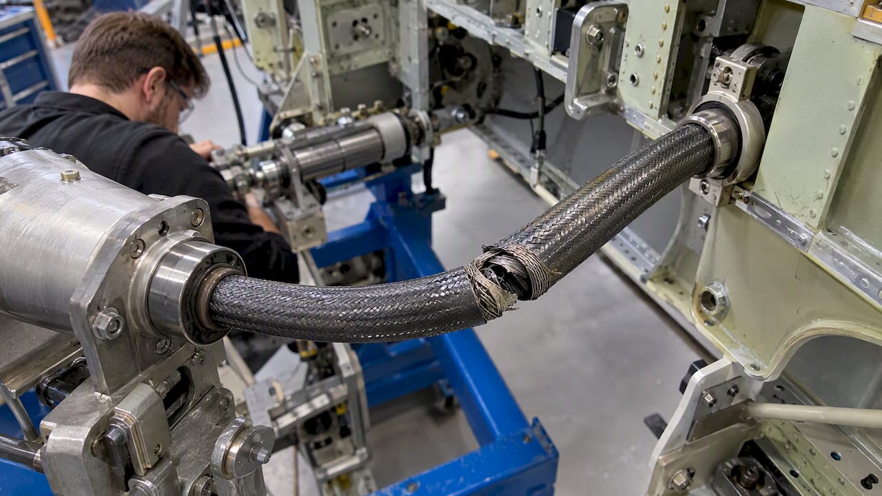
Aerospace applications raise the stakes on every step above. Safety margins, redundancy, and full documentation and traceability of materials and processes take priority over cost or schedule, which shifts the RCFA emphasis toward conservative design limits rather than reactive repair. In installations such as thrust reverser actuation, flap and slat actuation, or valve override systems, shafts operate within severe routing constraints that add bending stress on top of torsional load, making fillet geometry and alignment tolerance especially critical. Synchronization shafts in confined bays face similar demands, where our custom shaft configuration guidance supports specification work for constrained geometries.
— Uli
Engineering support for custom flexible-shaft solutions
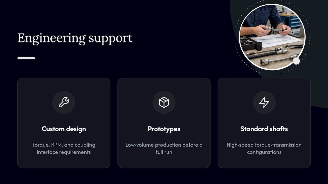
We design and manufacture custom and standard flexible shafts, including engineering support for torque, RPM, and coupling interface requirements. When an RCFA points to a design limitation, when operating conditions demand a revised specification, or when a project needs prototypes or low-volume production before committing to a full run, our Sonderlösungen und Prototypen line addresses that need directly. For standard torque-transmission components, our Antriebs- und Werkzeugwellen page outlines available configurations for high-speed applications.
FAQ
What is the most common cause of flexible shaft failure?
Fatigue from cyclic bending and torsional stress is the most common cause, often worsened by misalignment, stress concentrations at geometric features, or corrosion, as confirmed in a review of shaft failure mechanisms. Final fracture typically occurs only after a crack has grown progressively over an extended period of cyclic loading.
How can I tell fatigue failure apart from overload failure?
Fatigue fractures show beach marks and a clear crack-origin point, while overload fractures display a coarse, granular surface without progressive crack-growth features, according to practical shaft failure guidance. Correlating the fracture appearance with operating history confirms which mechanism applies.
What early warning signs indicate a developing fatigue crack?
A slow crack growing under cyclic load often produces gradual changes in vibration signature, abnormal bearing wear, or audible changes before final fracture occurs. Monitoring vibration trends and conducting periodic visual or NDT inspection are the most reliable ways to catch these signs before failure.
When should I send a failed shaft to a lab instead of relying on field inspection?
Escalate to lab analysis when the fracture origin is ambiguous, when the failure recurs across multiple units, or when a design or material change is under consideration. Lab techniques such as SEM fractography and metallography resolve details that field inspection cannot, as described in shaft failure mode research.
Can misalignment alone cause a flexible shaft to fail?
Misalignment rarely causes immediate failure but significantly increases cyclic bending stress, which accelerates fatigue crack initiation over time. Correcting alignment is frequently the most effective single intervention for extending service life, particularly in overhung shaft configurations as noted in root-cause analysis of pump shaft failures.
For installation-specific guidance or a review of a failed component, reach out through our contact page.
Sources
- Review: Failure modes, mechanisms and causes of shafts in mechanical equipment
- What Causes Shaft Failure?
- What is the Root Cause of Shaft Failure? | Pumps & Systems
Recommended
- 3 Engineering Priorities for Flexible Shaft Vibration in Aerospace
- 4 Checks OEM Engineers Must Run for Axial Thrust in Flexible Shafts
- Five Tests That Reveal Flexible Shaft Faults for Aerospace Engineers
- Flexible Shaft Maintenance Process for Peak Performance
Related Topics
Send your spec inquiry
Custom flexible shafts for your application — we quote within 1 working day.