
Shaft Coupling Types Explained for Industrial Engineers
15 June 2026TL;DR:
- Flexible shaft couplings are essential in accommodating residual misalignment, vibration, and thermal expansion in machinery, improving system reliability. Rigid couplings require near-perfect alignment and are suited for precise, low-misalignment conditions, while flexible types handle dynamic loads and misalignments effectively. Proper coupling selection depends on torque, speed, misalignment, vibration, and environmental factors, with flexible couplings being the default choice for most industrial and aerospace applications.
A shaft coupling is a mechanical device that connects two rotating shafts to transmit torque while accommodating misalignment between them. In real-world machinery, perfect shaft alignment is an engineering ideal, not a guaranteed outcome. Bearing wear, thermal expansion, and foundation settling all introduce residual misalignment over time. Understanding shaft coupling types explained through the lens of mechanical design constraints, not just catalog specifications, is what separates reliable installations from premature failures. This guide covers the primary shaft coupling classifications, their performance characteristics, and the engineering factors that determine the right choice for industrial and aerospace applications.
What are the main shaft coupling types and their mechanical principles?
Shaft couplings divide into two primary categories: rigid and flexible. Each category contains several subtypes with distinct operating principles, misalignment tolerances, and mechanical behavior.
Rigid Couplings
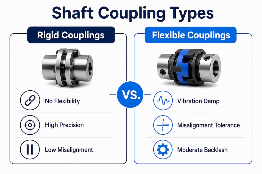
Rigid couplings transmit torque with no flexibility and require 0.05 mm TIR or better shaft alignment. They are suited for shafts sharing a common bearing support, such as line shafts in precision machine tools. Any misalignment beyond tolerance generates radial loads that accelerate bearing wear.
Jaw (Elastomeric Spider) Couplings
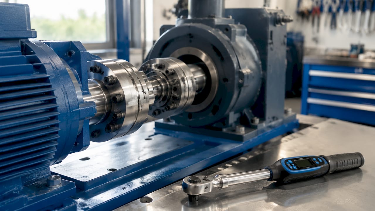
Jaw couplings use an elastomeric spider element seated between two metal hubs. This design provides moderate angular and parallel misalignment tolerance with good vibration damping. The elastomer absorbs shock loads and reduces transmitted vibration, making jaw couplings a common choice for motor-to-pump and motor-to-gearbox connections.
Disc Couplings
Disc couplings use thin metallic flexure discs to transmit torque. They provide zero-backlash, high torsional stiffness and operate at speeds up to 30,000 RPM. Disc couplings are the standard choice for high-speed servo drives, turbomachinery, and aerospace actuation systems where positional accuracy is critical.
Gear Couplings
Gear couplings transmit high torque through meshing gear teeth and tolerate both angular and parallel misalignment. They are used in heavy industrial drives, rolling mills, and marine propulsion systems where torque density is the primary requirement.
Bellows and Beam Couplings
- Bellows couplings use a thin-walled metallic bellows to provide torsional stiffness with low inertia, suited for precision instrumentation and encoder drives.
- Beam couplings use a helical cut in a single aluminum or stainless steel body to provide flexibility in multiple planes, commonly used in light-duty servo and stepper motor applications.
Each type represents a specific trade-off between flexibility, torsional stiffness, backlash, and load capacity. Selecting the wrong type for an application does not just reduce performance. It accelerates component wear across the entire drive train.
How do shaft coupling types compare on key performance metrics?
Comparing different shaft coupling types on a consistent set of metrics is the most direct path to a sound selection decision. The table below summarizes the primary performance parameters for the six most common coupling types.
| Coupling Type | Torque Range | Max RPM | Misalignment Tolerance | Backlash | Vibration Damping | Typical Cost |
|---|---|---|---|---|---|---|
| Rigid | Low to high | 3,000–10,000 | Near zero | None | None | Low |
| Jaw (Elastomeric) | Low to medium | 4,000–8,000 | Angular + parallel | 1°–3° | Excellent | $30–$80 |
| Disc | Medium to high | Up to 30,000 | Angular + axial | Zero | Poor | $200–$600 |
| Gear | High to very high | 3,000–6,000 | Angular + parallel | Slight | Low | High |
| Bellows | Low to medium | Up to 10,000 | Angular + axial | Zero | Low | Medium |
| Beam | Very low to low | Up to 5,000 | Angular + parallel | Near zero | Low | Low to medium |
Jaw couplings cost $30–$80 for 24 mm bores and provide 1°–3° of backlash with excellent vibration damping. Disc couplings cost $200–$600 and deliver zero backlash at speeds up to 30,000 RPM. That cost differential reflects a fundamental design trade-off: elastomeric flexibility versus metallic precision.
Vibration damping is a critical differentiator that the table makes clear. Disc and bellows couplings provide zero backlash but absorb almost no vibration. Jaw couplings absorb shock and vibration but introduce measurable backlash. For CNC machining centers where zero-backlash couplings directly affect positioning accuracy, disc or bellows types are the correct choice. For pump drives and conveyor systems where vibration isolation matters more than positional precision, jaw couplings deliver better long-term reliability.
Pro Tip: When comparing coupling types, check the manufacturer’s misalignment rating at operating speed, not just at zero RPM. Misalignment tolerance often decreases significantly at higher rotational speeds, which changes the selection outcome.
What engineering factors determine the right coupling for your application?
Coupling selection requires more than matching torque ratings. Several engineering factors interact to determine whether a coupling will perform reliably over its service life.
Service Factor Application
Couplings are not sized on peak torque alone. Service factors range from 1.0–1.5 for steady-state loads and from 2.5–4.0 for highly variable or reversing loads. A pump drive running at constant speed uses a service factor of 1.25. A crusher or shredder with high shock loading requires a service factor of 3.0 or higher. Omitting this calculation leads to coupling failures that damage downstream components, including gearboxes and motor bearings.
Misalignment as an Engineering Reality
Laser alignment cannot guarantee perfect collinearity. Typical residual misalignment in well-aligned installations ranges from 0.05°–0.5° angular and 0.05–0.25 mm parallel. These values are small but not negligible. Ignoring residual misalignment causes bearing life to drop from 20,000+ hours to under 12 months due to cyclic radial loading. This is the primary reason flexible couplings are the correct default choice for most motor-driven equipment.
Key selection factors to evaluate before specifying a coupling:
- Torque and speed: Confirm the coupling’s rated torque at operating RPM, not just static torque capacity.
- Misalignment type and magnitude: Distinguish between angular, parallel, and axial misalignment. Different coupling types accommodate each differently.
- Backlash tolerance: Servo drives and positioning systems require zero-backlash designs. Pump and fan drives can tolerate slight backlash.
- Vibration profile: Identify whether the application generates shock loads, torsional oscillations, or steady-state vibration. Match the coupling’s damping characteristics accordingly.
- Environmental conditions: Elastomeric spiders last 5–7 years under normal conditions but degrade faster in high-temperature or chemically aggressive environments. Metallic couplings are more durable in harsh conditions.
- Maintenance access: Spacer-type coupling designs allow component removal without realigning the entire drive assembly, reducing maintenance downtime significantly.
Aerospace-Specific Considerations
In aerospace applications, including thrust reverser actuation, flap and slat drive systems, and valve override mechanisms, coupling selection adds further constraints. Weight, inertia, and torsional stiffness all affect system response time and control authority. Disc and bellows couplings are preferred in these environments because they provide zero backlash and predictable torsional behavior. Synchronization shafts in multi-actuator systems require couplings with matched torsional stiffness to prevent phase lag between actuators.
Pro Tip: For motor-to-gearbox connections in aerospace actuation systems, specify the coupling’s torsional stiffness in Nm/rad and confirm it matches the control system’s bandwidth requirements. A coupling that is too soft introduces phase lag that degrades closed-loop control performance.
Rigid vs. flexible shaft couplings: when should each be used?
The distinction between rigid and flexible shaft couplings is the most consequential decision in the selection process. Each category has specific conditions under which it is the correct choice.
When rigid couplings are appropriate:
- Both shafts share a common bearing support, eliminating relative movement between shaft centerlines.
- The application requires zero backlash and maximum torsional stiffness, such as precision grinding spindles.
- Shaft alignment can be maintained within 0.05 mm TIR throughout the operating cycle, including thermal effects.
- The drive system generates no shock loads or vibration that would propagate through a rigid connection.
When flexible couplings are the correct choice:
- Shafts are supported by separate bearing housings, making residual misalignment unavoidable.
- The drive system includes motors, pumps, or compressors that generate vibration or torsional oscillations.
- Thermal expansion during operation changes the relative position of shaft centerlines.
- Maintenance schedules require periodic elastomer replacement without full drive disassembly.
Flexible couplings damp vibration and absorb misalignment through elastomeric or metallic membrane elements, protecting upstream bearings and seals. The advantages of flexible coupling designs extend beyond misalignment tolerance. They reduce noise, extend bearing life, and lower the risk of fatigue failure in connected shafts.
Choosing a rigid coupling where a flexible coupling is required does not just reduce system life. It transfers misalignment-induced loads directly into bearings and seals, causing failures that are often misdiagnosed as bearing quality issues rather than coupling selection errors. The rigid vs. flexible shaft selection decision should be made at the system design stage, not after the first bearing replacement.
Key takeaways
Flexible couplings are the correct default for most motor-driven industrial and aerospace applications because residual misalignment is unavoidable and rigid connections accelerate bearing failure.
| Point | Details |
|---|---|
| Rigid couplings require near-perfect alignment | Tolerance is 0.05 mm TIR or better; any deviation generates destructive radial loads on bearings. |
| Service factor is non-negotiable | Apply 1.0–1.5 for steady loads and 2.5–4.0 for shock or reversing loads to prevent premature failure. |
| Disc couplings suit high-speed precision drives | Zero backlash and 30,000 RPM capability make them the standard for servo and turbomachinery applications. |
| Elastomeric elements have a finite service life | Jaw coupling spiders last 5–7 years under normal conditions; inspect more frequently in harsh environments. |
| Spacer designs reduce maintenance downtime | Spacer-type couplings allow component removal without realigning the full drive assembly. |
Coupling selection: what experience actually teaches
By Uli
After working with flexible shaft systems across industrial manufacturing and aerospace applications, the most consistent mistake I see is treating coupling selection as a catalog exercise. Engineers match the torque rating, check the bore size, and move on. The service factor calculation gets skipped because the application “looks straightforward.”
That assumption fails most often on equipment with variable loads. A conveyor that starts under full load, a pump with frequent cycling, or a gearbox driving an intermittent mechanism all impose dynamic loads that multiply the nominal torque by factors that rigid catalog matching cannot capture. The coupling fails, the downstream gearbox takes the impact, and the root cause gets attributed to the gearbox rather than the coupling specification.
The second consistent issue is misalignment optimism. Laser alignment is the correct tool, but it measures cold, static alignment. Thermal growth during operation shifts shaft centerlines in ways that are application-specific and often not accounted for in the coupling selection. Flexible couplings with adequate misalignment tolerance are not a compromise. They are the correct engineering response to a physical reality that no alignment procedure eliminates.
For aerospace actuation systems, I would add one more consideration: torsional stiffness matching. The coupling is part of the control loop. A coupling that is too compliant introduces phase lag that the control system must compensate for, and that compensation has limits. Specifying torsional stiffness in Nm/rad and confirming it against the control bandwidth is not optional in closed-loop actuation systems.
— Uli
Flexible shaft solutions from Biax-flexwellen
Biax-flexwellen designs and manufactures industrial flexible shafts and drive solutions for applications where standard rigid couplings cannot accommodate the required misalignment, access constraints, or vibration profile. For deburring, grinding, polishing, and finishing operations in confined or hard-to-reach spaces, Biax-flexwellen’s flexible shaft systems transmit torque reliably without requiring precise shaft collinearity. Machine builders working on industrial manufacturing applications and robotics integrators can consult Biax-flexwellen for standard components and custom configurations matched to specific torque, RPM, and coupling interface requirements. Engineers looking to improve machine design efficiency through flexible drive solutions are encouraged to contact Biax-flexwellen directly via the website contact form.
FAQ
What is the difference between rigid and flexible shaft couplings?
Rigid couplings transmit torque with no flexibility and require near-perfect shaft alignment within 0.05 mm TIR. Flexible couplings accommodate angular, parallel, and axial misalignment through elastomeric or metallic flexure elements, protecting bearings and seals from misalignment-induced loads.
Which shaft coupling type provides zero backlash?
Disc couplings and bellows couplings both provide zero backlash. Disc couplings are preferred for high-speed applications up to 30,000 RPM, while bellows couplings are used in precision instrumentation and encoder drives where low inertia is also required.
How does misalignment affect bearing life?
Residual misalignment imposes cyclic radial loads on bearings. Without a flexible coupling to absorb this misalignment, bearing life drops from 20,000+ hours to under 12 months in typical industrial installations.
What service factor should be applied to coupling selection?
Apply a service factor of 1.0–1.5 for steady-state loads and 2.5–4.0 for highly variable, shock, or reversing loads. Skipping this calculation is the most common cause of premature coupling failure in industrial drives.
How long do elastomeric coupling elements last?
Elastomeric spider elements in jaw couplings last approximately 5–7 years under normal operating conditions. High temperatures, chemical exposure, and shock loading accelerate degradation and require more frequent inspection intervals.
Recommended
- The Role of Shaft Couplings in Power Transmission
- 7 Practical Examples of Shaft Drive Solutions for Engineers
- Advantages of flexible coupling: a mechanical engineer’s guide
- Flexible shaft guide: Engineering compact drive solutions
Related Topics
Send your spec inquiry
Custom flexible shafts for your application — we quote within 1 working day.


