Shaft Coupling Interfaces Explained for Industrial Engineers
29 June 2026TL;DR:
- Shaft coupling interfaces connect rotating shafts to transmit torque while accommodating misalignment. Proper selection of coupling type, size, and service factor is essential to avoid premature failure and extend system life. Aerospace and confined environments favor metallic flex elements due to vibration and temperature challenges.
A shaft coupling interface is the mechanical connection point between two rotating shafts that transmits torque while accommodating misalignment and protecting adjacent components from dynamic loads. Understanding shaft coupling interfaces explained in full mechanical detail is the foundation for reliable power transmission in pumps, conveyors, aerospace actuators, and finishing machinery. The wrong interface type causes bearing failure, seal damage, and unplanned downtime. The right one can extend drivetrain service life well beyond 20,000 operating hours. This article covers the mechanical principles, interface types, selection criteria, and aerospace-specific design constraints engineers need to make informed coupling decisions.
What are the mechanical principles of shaft coupling interfaces?
Torque transmission through a coupling interface works by transferring rotational force from a driving shaft to a driven shaft across a mechanical connection. That connection must handle not only steady-state torque but also shock loads, torsional vibration, and the three primary forms of shaft misalignment: parallel (radial offset), angular (shaft centerline angle), and axial (end-float along the shaft axis).
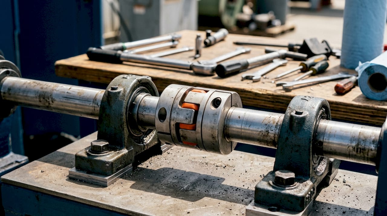
Misalignment is unavoidable in real installations. Thermal expansion shifts shaft centerlines as equipment reaches operating temperature. Foundation settling introduces angular offset over time. Even precision-machined housings carry manufacturing tolerances that accumulate. A coupling interface that cannot absorb these deviations transfers cyclic radial loads directly into bearings and seals. Even 0.1 mm of parallel misalignment without a compliant element causes rapid bearing failure within months rather than years. That single data point explains why flexible coupling interfaces are the default choice in most industrial drives.
The mechanical elements that absorb misalignment vary by coupling type. Elastomeric spider elements in jaw couplings deform under load to accommodate offset. Disc packs in disc couplings flex axially and angularly while transmitting high torque. Gear couplings use crowned tooth profiles to allow angular articulation. Each mechanism has a defined compliance range, and operating outside that range eliminates the protective benefit.
The service factor is the multiplier applied to nominal torque when sizing a coupling. A service factor of 2.0 is the standard recommendation for general industrial duty, providing margin for shock and peak loads without excessive oversizing. A service factor of 1.0 is appropriate only for smooth, constant-load drives with no shock. Heavy-duty crushers, reciprocating compressors, and reversing drives typically require service factors of 3.0 or higher.
Pro Tip: Always calculate the service factor before selecting a coupling bore size. Undersizing by even one torque class is the most common cause of premature elastomer fatigue in jaw couplings.
Properly sized couplings operate for 20,000 or more hours in pump and conveyor applications before elastomer or disc pack replacement is needed. Disc packs in low-vibration environments can exceed 100,000 hours. These figures assume correct alignment at installation and periodic inspection.
What are the main shaft coupling interface types?
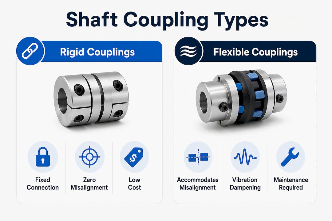
The types of coupling interfaces used in industrial machinery fall into two broad categories: rigid and flexible. Each category contains several subtypes with distinct mechanical characteristics.
Rigid couplings
Rigid couplings create a fixed, zero-compliance connection between two shafts. They transmit torque with no angular or parallel flexibility. Rigid couplings require alignment within 0.05 mm TIR (total indicator reading). Any deviation beyond that threshold transfers bending moments directly into shaft bearings and seals, accelerating failure. Rigid interfaces are appropriate only where shafts are precisely aligned and held in position by stiff, thermally stable housings.
Rigid couplings are low cost, typically $15–$40 for a 24 mm bore, and have no wearing elements. Their RPM ceiling is approximately 5,000 RPM. The absence of a compliant element is both their advantage and their primary limitation.
Flexible coupling subtypes
Flexible couplings introduce a compliant element between the two shaft hubs. The compliance absorbs misalignment, damps torsional vibration, and isolates the driving machine from shock loads generated by the driven machine.
- Jaw (spider) couplings: Accommodate up to 0.4 mm parallel and 1° angular misalignment. The elastomeric spider element is replaceable without moving either hub, which minimizes maintenance downtime. This is the most widely used flexible coupling type in light to medium industrial drives.
- Disc couplings: Use thin metallic disc packs to transmit torque. They handle speeds up to 30,000 RPM and offer zero backlash, making them the preferred choice for high-speed spindles and servo drives. Cost for a 24 mm bore disc coupling runs $200–$600.
- Gear couplings: Use crowned external and internal gear teeth to allow angular misalignment up to approximately 1.5°. They handle high torque in compact envelopes but require periodic lubrication.
- Grid couplings: Use a spring-steel grid element that provides shock absorption and torsional damping. Common in heavy industrial drives such as crushers and mills.
- Chain couplings: Use a duplex roller chain connecting two sprocket hubs. Simple, low cost, and tolerant of parallel misalignment, but require lubrication and generate more noise than elastomeric types.
The table below summarizes key performance characteristics across the main interface types.
| Coupling type | Parallel misalignment | Angular misalignment | Max RPM | Maintenance interval |
|---|---|---|---|---|
| Rigid | 0.05 mm TIR | Near zero | ~5,000 | None (no wearing parts) |
| Jaw (spider) | 0.4 mm | 1° | ~4,000–6,000 | Spider replacement at wear |
| Disc | 0.1–0.3 mm | 0.5°–1° | Up to 30,000 | Inspect disc packs periodically |
| Gear | 0.1–0.5 mm | Up to 1.5° | ~3,500–5,000 | Lubrication every 6–12 months |
| Grid | 0.3–0.5 mm | 0.5°–1° | ~3,600 | Lubrication and grid inspection |
Pro Tip: The replaceable spider element in jaw couplings is one of the most maintenance-friendly features in industrial coupling design. Schedule spider inspections at every 4,000–6,000 operating hours to catch wear before it causes hub contact.
Material selection for hubs and flexible elements directly affects performance. Cast iron hubs are standard for general industrial use. Steel hubs are specified for high-torque or high-speed applications. Aluminum hubs reduce rotating inertia in servo systems. Elastomeric spider elements are available in urethane (higher torque, lower damping) and rubber (lower torque, higher damping), and the choice affects both torsional stiffness and thermal operating range.
How do you select and size shaft coupling interfaces?
Coupling selection follows a defined sequence. Skipping steps is the primary cause of premature failure in field installations.
- Calculate design torque. Multiply the nominal torque by the service factor appropriate for the application. A centrifugal pump with a smooth load profile uses a service factor of 1.5. A reciprocating compressor with shock loading uses 3.0 or higher.
- Quantify misalignment. Measure or estimate parallel, angular, and axial misalignment at operating temperature, not just at cold installation. Thermal growth in large pump sets can shift shaft centerlines by 0.3–0.5 mm.
- Determine speed range. Confirm the coupling’s rated RPM exceeds the maximum operating speed with margin. Disc couplings are the correct choice for drives above 6,000 RPM.
- Evaluate environmental conditions. Chemical exposure, temperature extremes, and wash-down requirements influence elastomer material selection and hub coating.
- Confirm bore and keyway dimensions. Coupling bore must match shaft diameter within the manufacturer’s tolerance. Interference fits are standard for high-torque applications. Clearance fits with keyways are common in general industrial drives.
Flexible couplings are the correct choice whenever vibration, thermal expansion, or minor misalignment are present. Rigid couplings are appropriate only for precision-aligned, thermally stable shaft systems where the housing constrains both shafts rigidly. Neither type is universally superior. The operating conditions define the correct interface.
Common installation errors include over-tightening set screws without checking bore fit, aligning shafts cold without accounting for thermal growth, and installing jaw couplings with mismatched spider durometers. Each error reduces coupling life and transfers load to adjacent bearings.
Pro Tip: Verify shaft alignment after the system reaches operating temperature. Cold alignment alone does not account for thermal growth in motor frames and pump casings, and the resulting misalignment is the leading cause of early bearing failure in coupled drives.
Correct coupling interface selection directly extends bearing and seal service life. Oversizing a coupling adds cost and rotating inertia but does not harm the system. Undersizing causes fatigue failure of the flexible element, which then transmits shock loads to bearings.
What are the design constraints for aerospace and confined environments?
Aerospace shaft coupling interfaces operate under constraints that do not apply to standard industrial drives. Weight, envelope size, vibration spectrum, and temperature range are all tightly controlled by system-level requirements.
- Weight and inertia limits: Aerospace actuation systems specify maximum component mass. Aluminum and titanium hubs replace steel where torque levels permit. Every gram saved in a rotating component reduces dynamic loading on the airframe structure.
- Envelope constraints: Thrust reverser actuation shafts, flap and slat drive systems, and valve override mechanisms route through confined airframe cavities. Coupling interfaces in these systems must fit within defined cross-sections, often with no access for in-service lubrication.
- Vibration and thermal cycling: Aerospace couplings experience broadband vibration from engine excitation and aerodynamic buffeting. Thermal cycling from ground to altitude conditions spans a wide temperature range. Disc couplings and metallic flexible elements are preferred over elastomeric types in these environments because elastomers degrade under sustained vibration and temperature extremes.
- Synchronization shafts: Flap and slat systems use synchronization shafts to coordinate surface deflection across the wing span. The coupling interfaces along these shafts must maintain angular accuracy while accommodating structural flex. Backlash in any interface accumulates across multiple stations and produces surface position error.
- Precision manufacturing tolerances: Aerospace coupling interfaces are manufactured to tighter tolerances than industrial equivalents. Bore concentricity, face runout, and balance grades are specified to levels that require grinding rather than turning.
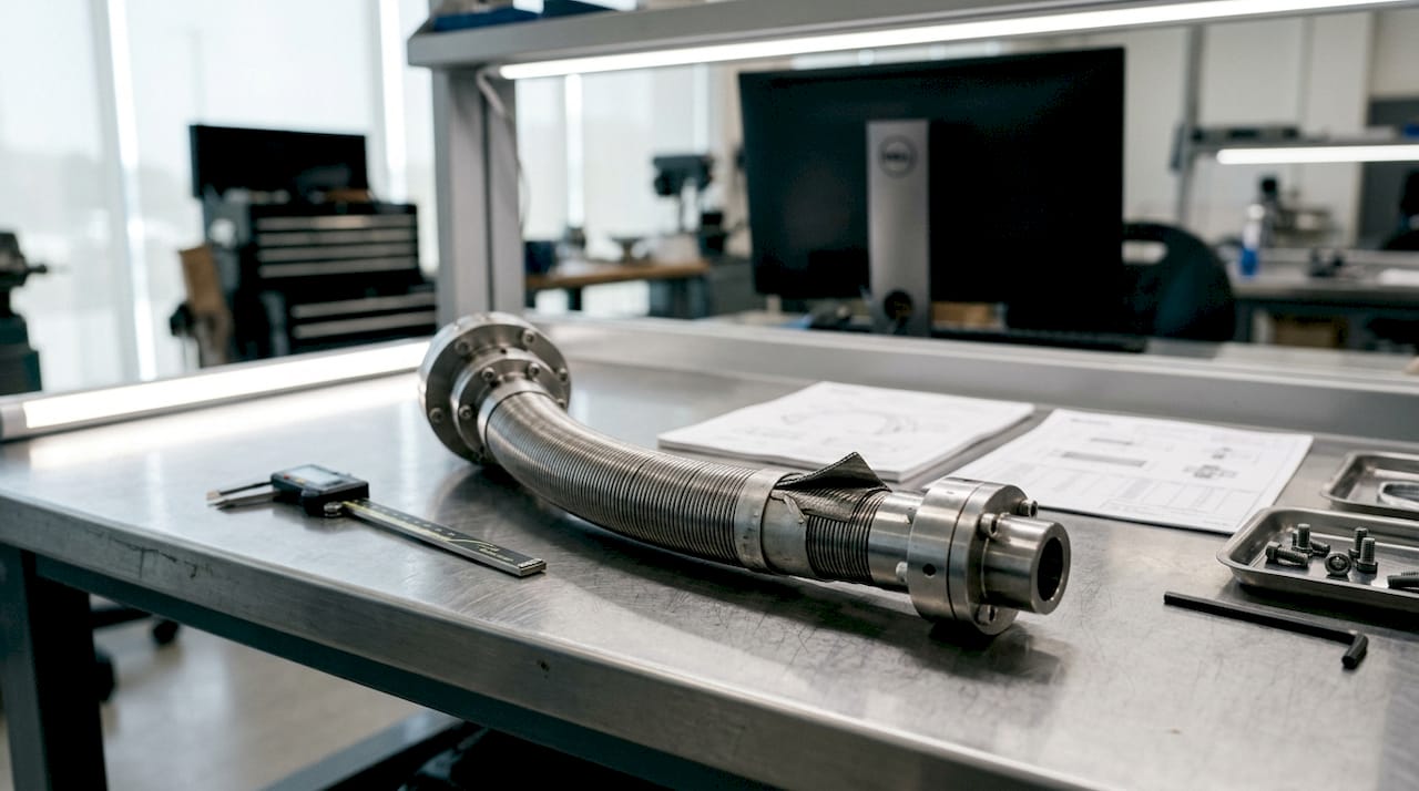
Compact drive trains in industrial finishing machinery share some of these constraints. Deburring, grinding, and polishing spindles mounted on robotic arms or multi-axis fixtures operate in confined spaces where standard flange couplings do not fit. Flexible shaft solutions route torque around obstacles without requiring inline shaft alignment, which eliminates the coupling interface misalignment problem entirely in some configurations.
The role of shaft couplings in power transmission in both aerospace and confined industrial environments comes down to the same principle: the interface must transmit the required torque reliably within the available space, under the actual operating conditions, for the required service life.
Key Takeaways
Correct shaft coupling interface selection requires matching the coupling type, service factor, and misalignment tolerance to the actual operating conditions, not the nominal design conditions.
| Point | Details |
|---|---|
| Misalignment causes bearing failure | Even 0.1 mm of parallel misalignment without a compliant coupling leads to bearing failure within months. |
| Service factor determines sizing | Apply a service factor of 2.0 for general industrial duty; increase to 3.0 or higher for shock and reversing loads. |
| Disc couplings handle high speeds | Disc couplings operate up to 30,000 RPM and are the correct choice for servo and high-speed spindle drives. |
| Jaw couplings offer easy maintenance | The spider element is replaceable without moving hubs, reducing downtime during scheduled maintenance. |
| Aerospace interfaces require metallic elements | Elastomeric couplings degrade under aerospace vibration and thermal cycling; disc or metallic flex elements are preferred. |
What I’ve learned from specifying coupling interfaces in the field
By Uli
The most consistent mistake I see in coupling selection is treating alignment as a one-time installation task. Engineers align shafts cold, record the numbers, and consider the job done. The coupling then operates for months in a misaligned condition because no one measured the shaft positions at operating temperature. Thermal growth in motor frames and pump casings is real and predictable. It should be calculated before the coupling is specified, not discovered after the first bearing replacement.
The second pattern I see regularly is defaulting to rigid couplings because they are cheap and simple. Rigid couplings are the right answer in a narrow set of conditions: precision-aligned, thermally stable, stiffly supported shafts. Outside those conditions, the cost saving on the coupling is paid back many times over in bearing replacements and unplanned downtime. A jaw coupling that costs $80 more than a rigid sleeve coupling will protect $600 worth of bearings on each side of the drive.
Oversizing with service factors is underused. Engineers calculate nominal torque, select the coupling that matches it, and move on. A service factor of 2.0 adds very little cost and provides meaningful protection against shock loads that are difficult to quantify at the design stage. The coupling is the cheapest component in the drivetrain. Protecting the motor and gearbox with a larger coupling is straightforward engineering economics.
One area where I think conventional guidance falls short is aerospace and confined industrial environments. Standard coupling selection charts assume inline shaft configurations with accessible installation space. Flexible shaft solutions that route torque around obstacles remove the alignment problem from the equation entirely. For finishing and machining applications on robotic or multi-axis platforms, that approach is often more reliable than any inline coupling interface.
— Uli
Biax-flexwellen’s engineering support for shaft coupling applications
Biax-flexwellen designs and manufactures flexible shaft and drive solutions for industrial applications where standard inline coupling interfaces are not practical. For machine builders working with confined installation spaces, multi-axis finishing systems, or applications requiring torque transmission around obstacles, flexible shaft applications provide an alternative to conventional coupling interfaces. Engineers specifying drives for deburring, grinding, polishing, or aerospace actuation can use the rigid vs. flexible shaft selection guide to evaluate which approach fits their torque, RPM, and installation requirements. For application-specific questions on coupling interfaces, torque requirements, or custom shaft configurations, contact the Biax-flexwellen engineering team directly at biax-flexwellen.de/en/contact/.
FAQ
What is a shaft coupling interface?
A shaft coupling interface is the mechanical connection between two rotating shafts that transmits torque while accommodating misalignment and protecting adjacent components from dynamic loads.
When should a flexible coupling be used instead of a rigid coupling?
Flexible couplings are required whenever vibration, thermal expansion, or shaft misalignment is present. Rigid couplings are appropriate only for precision-aligned, thermally stable shaft systems.
What service factor should be applied for general industrial drives?
A service factor of 2.0 is the standard recommendation for general industrial duty. Higher values of 3.0 or above apply to shock-loaded or reversing drives such as reciprocating compressors and crushers.
How long do shaft couplings last in industrial applications?
Properly sized couplings operate for 20,000 or more hours in pump and conveyor applications. Disc pack couplings in low-vibration environments can exceed 100,000 hours before replacement is needed.
Why do aerospace shaft coupling interfaces use metallic flex elements?
Elastomeric elements degrade under the broadband vibration and thermal cycling conditions found in aerospace actuation systems. Metallic disc or flex elements maintain performance across the full operating temperature and vibration spectrum.
Recommended
- Shaft Coupling Types Explained for Industrial Engineers
- Flexible shaft guide: Engineering compact drive solutions
- Rigid vs flexible shafts: Selection guide for industrial drives
- The Role of Shaft Couplings in Power Transmission
Related Topics
Send your spec inquiry
Custom flexible shafts for your application — we quote within 1 working day.


